5 Installation and commissioning
38
HSD S.p.A. © - h0104k01a.fm291119
5.8.3 CANopen configuration
Access the dip-switches of the electronic device tab, as explained on page 35.
The servo motor communication protocol can be selected using dip-switch DSW1.
Only change the configuration of the dip-switches when the board is not powered up.
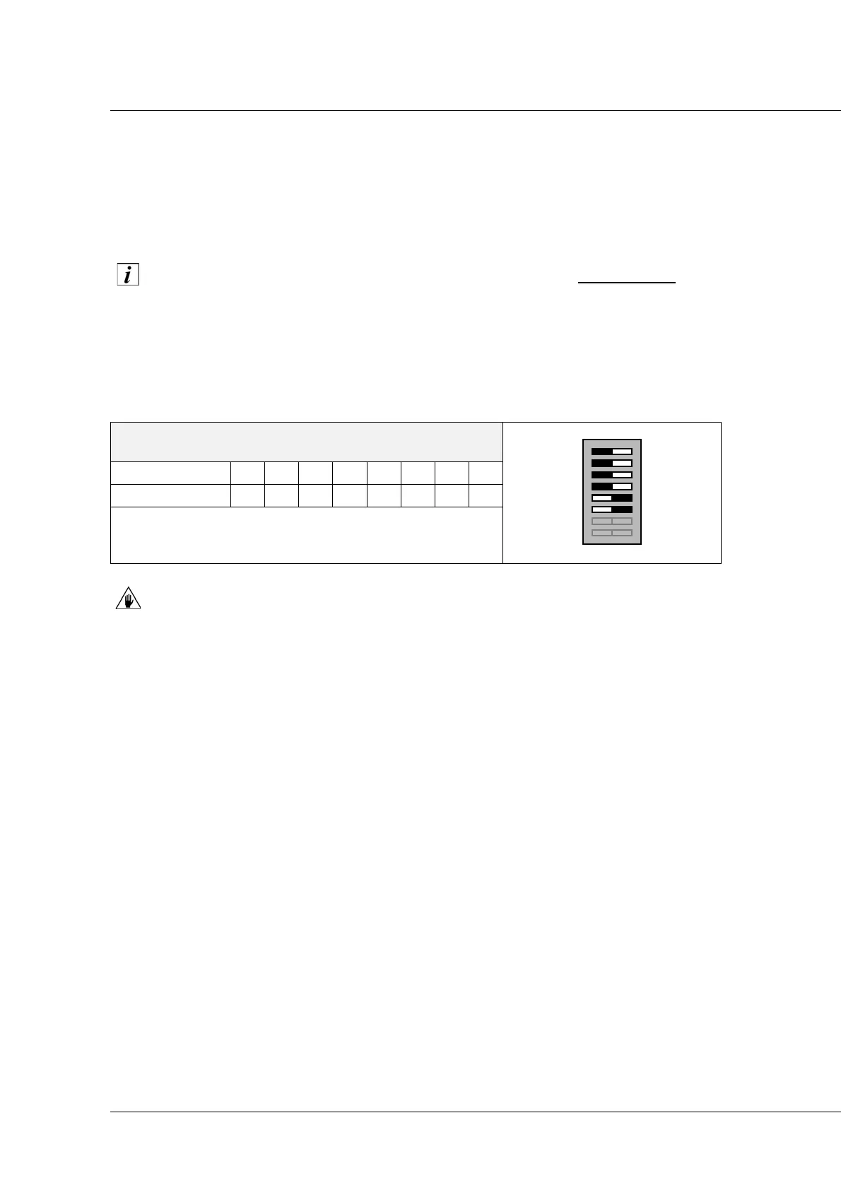
Dip-switch DSW1
To set the CANopen protocol on the servo-motor, configure the DSW1 switches as shown below.
Switches 7 and 8 are used to terminate the line, which are necessary to avoid signal flip
phenomena on the line.
If switches 7 and 8 are set differently (for example 7 ON and 8 OFF), the module may
not work correctly.
Dip-switch DSW2
Using dip-switch DSW2, it is possible to:
Set the node address;
Select standard or SM137C compatible operating mode;
Select one of the following additional functions:
• Bit-rate value setting;
• Set the high node address bits;
• Restore default settings.
DSW1
Switch 12345678
Position Off Off Off Off On On TT
T = Fieldbus line termination:
set Off if the Fieldbus continue,
set On at the Bus termination.