5 Installation and commissioning
32
HSD S.p.A. © - h0104k01a.fm291119
General regulations for using the electric connectors
Remember that the connector cannot sustain heavy twisting or axial strain, so it must be handled
with care and without using tools.
Before inserting/removing the connectors, make sure you can see them clearly so as to avoid
incorrect movements that could cause twisting or pressure that would damage the connector and
the relative support feet.
When inserting:
examine the connector carefully to understand the exact position of the pins;
gently push the connector into its socket, carefully pushing it in all the way;
after checking that the two connectors are perfectly coupled, use one hand to hold the inserted
connector still while you tighten the fixing screws with your other hand.
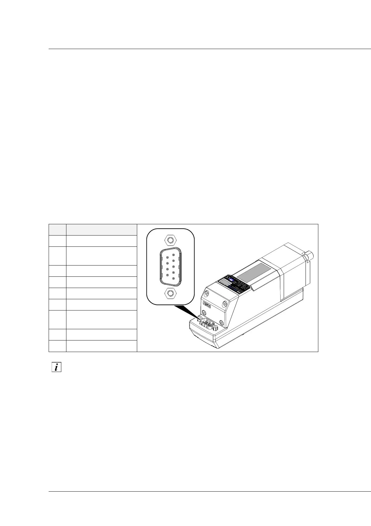
Electric connector
The motor is put in "safety mode" during switch-on and switch-off, and if there is a
communication failure with the PLC. Safety status means that the shaft is not moving. A
special software command must be used to restore normal operation.
Refer to the user manual "Technical characteristics and E-NETx connection” (for the E-NETx
communication protocol) issued by HSD S.p.A. to correctly use the cable.
PIN
Signal user side view
1 GND Logic
2
FB-
CAN_L
3 GND Shield
4GND Power
5GND Power
6V
DC
Logic
7
FB+
CAN_H
8V
DC
Power
9V
DC
Power