PQA400 - PQA823 - PQA824
EN - 115
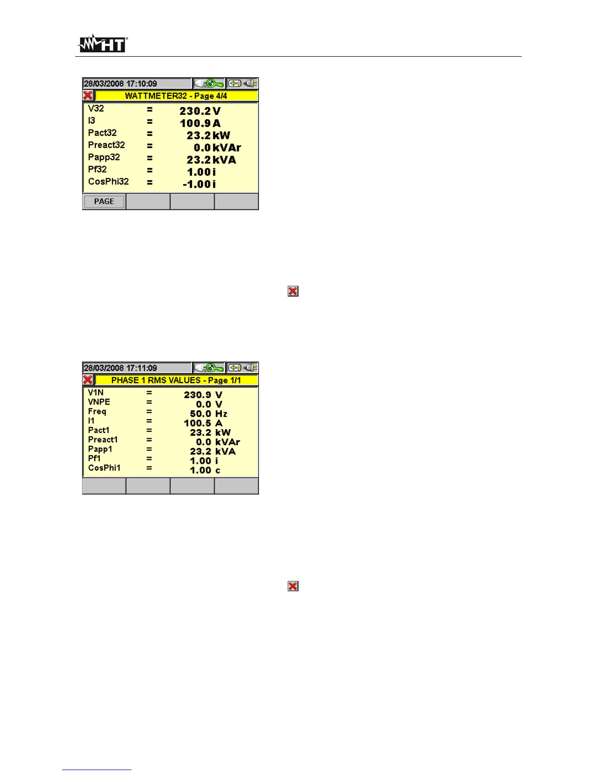
In this page, the following symbols are used:
V32 Phase L3 - Phase L2 Voltage
I3 Phase L3 Current
Patt32 Wattmeter 32 Active Power
Preatt32 Varmeter 32 Reactive Power
Papp32 Varmeter 32 Apparent Power
Pf32 Wattmeter 32 Power Factor
CosPhi32 Cosine of the Phase delay between the
Mattmeter 12 Voltage and Current fundamentals
Fig. 192: Page 4/4 of numeric values for Aron system
The following keys are active on this page:
The F1 key (or the PAG item on the display) advances to the following page of
saved values.
The ESC key (or the smart icon on the display) to exit the function and go back
to the “Recording analysis” page (Fig. 143).
In this page, the following symbols are used:
V1N Phase L1 - Neutral Voltage
VNPE Neutral - PE Voltage
Freq Frequency
I1 Phase L1 Current
Patt1 Phase L1 Active Power
Preatt1 Phase L1 Reactive Power
Papp1 Phase L1 Apparent Power
Pf1 Phase L1 Power Factor
CosPhi1 Cosine of the Phase angle between the Phase L1
Voltage and Current fundamentals
CosPhi represents the theoretical limit value which
can be reached by the Power factor if all harmonics
are eliminated from the electrical system. For
dimensioning a power factor correction system,
reference is usually made to the CosPhi parameter
value.
Fig. 193: Page 1/1 of numeric values for single-phase system
The following keys are active on this page:
The ESC key (or the smart icon
on the display) to exit the function and go back
to the “Recording analysis” page (Fig. 143).