PQA400 - PQA823 - PQA824
EN - 18
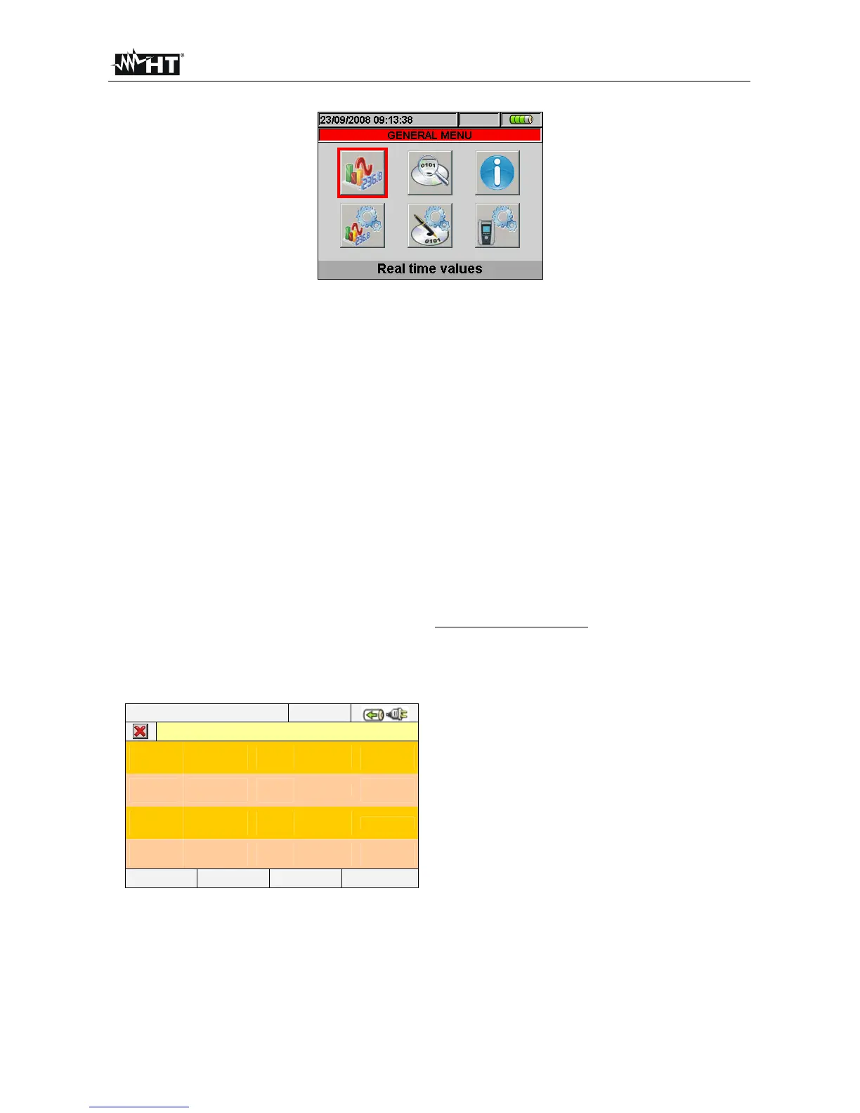
5.2. REAL TIME VALUES
Fig. 18: MENU GENERAL screen - Real time values section
In this section the real time measured values of parameters both on input channels and
internally calculated are shown by meter. In particular the following are shown:
1. AC TRMS voltages, currents and all kind of electrical parameters for any single phase
and total, Flicker values and voltages Unbalanced.
2. Voltage and current waveforms for any single phase and total.
3. Voltage and current harmonics up to 49
th
component for any single phase and total
both in numerical and histograms graphical format in absolute or percentage value with
respect to each fundamental signal.
4. Vectorial diagrams of each voltage and current with the respective phase angles in
order to define the correct nature of system loads under test.
Further in this manual the expression “Page x/y” will be used, to indicate that the current page
number (x) and the total number of pages (y) depend on the instrument settings. Pressing
cyclically F1 key or arrow keys left of right the meter shows the other pages of TRMS
measured values which are described in below pictures. Pressing ESC key to go back to
previous screens or back to GENERAL MENU
5.2.1. 4-wire three phase system – Screens sequence
12/09/2006 – 16:55:10
TOTAL RMS VALUES – Page x/y
V1N
0.0
V2N
0.0
V3N
0.0
VNPE
0.0
V
V12
0.0
V23
0.0
V31
0.0
V
NEG%
0.0
ZERO%
0.0
SEQ
000
Hz
0.0
I1
0.0
I2
0.0
I3
0.0
IN
0.0 A
PAGE SCOPE HARM VECTORS
PARAMETERS CAPTION
V1N Phase-Neutral voltage L1 phase
V2N Phase-Neutral voltage L2 phase
V3N Phase-Neutral voltage L3 phase
VNPE Neutral-Ground voltage
V12 Phase L1 – Phase L2 voltage
V23 Phase L2 – Phase L3 voltage
V23 Phase L3 – Phase L1 voltage
NEG% Unbalance percentage of negative tern
ZERO% Unbalance percentage of zero tern
SEQ phases sequence indication as:
”123” = > Corrected
”132” = > Reversed
”023” = > Null voltage on the Black wire
”103” = > Null voltage on the Red wire
”120” = > Null voltage on the Brown wire
”100” = > Null voltage on the Red and Brown wires
”020” = > Null voltage on the Black and Brown wires
”003” = > Null voltage on the Black and Red wires
Hz Frequency
I1 Current on L1 phase
I2 Current on L2 phase
I3 Current on L3 phase
IN Current on Neutral
Fig. 19: Page of numerical values