PQA400 - PQA823 - PQA824
EN - 36
12/09/2006 – 16:55:10
PHASE1 DIAGRAM – Page 1/6
V1^ I1
60.0°
PAGE
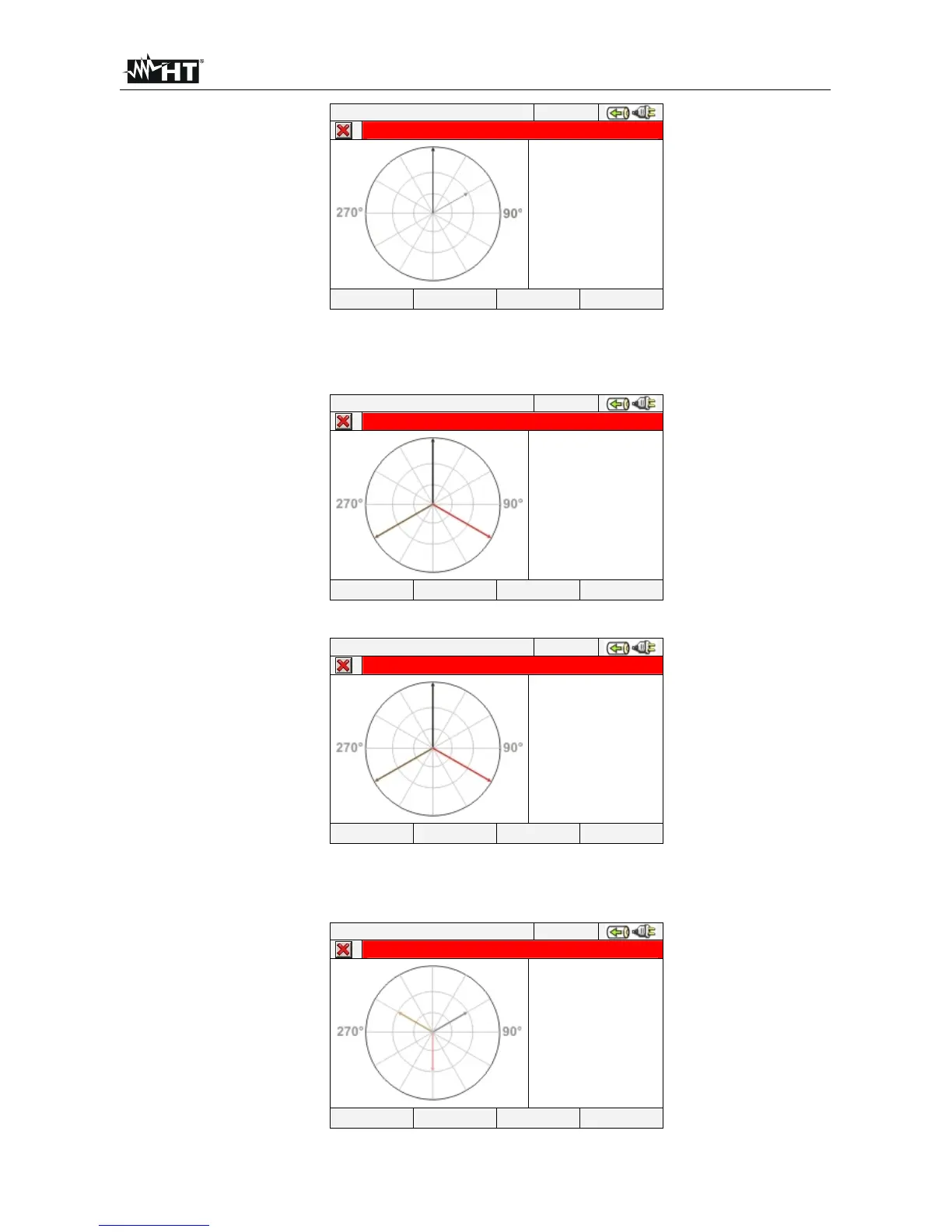
Fig. 73: Vectorial diagram total for Single phase system
The vectorial diagram of single voltages depending on the type of selected systems as
shown in below screens:
12/09/2006 – 16:55:10
VOLTAGES DIAGRAM – Page 2/6
NEG 0.0%
ZERO
0.0%
V1^ V2
120.0°
V2^ V3
120.0°
V3^ V1
120.0°
PAGE
Fig. 74: Vectorial voltage diagram for 4-wire system
12/09/2006 – 16:55:10
VOLTAGES DIAGRAM – Page 2/6
NEG 0.0%
ZERO
0.0%
V12^ V23
120.0°
V23^ V31
120.0°
V31^ V12
120.0°
PAGE
Fig. 75: Vectorial voltage diagram for 3-wire and ARON systems
The vectorial diagram of currents for 4-wire, 3-wire and ARON systems as shown in:
12/09/2006 – 16:55:10
CURRENTS DIAGRAM – Page 3/6
I1^ I2
120.0°
I2^ I3
120.0°
I3^ I1
120.0°
PAGE
Fig. 76: Vectorial currents diagram for 4-wire, 3-wire and ARON systems