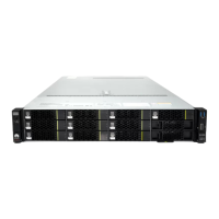
Table 7-5 Power cables to be installed onsite (in a DC cabinet)
Cable One End The Other End
Connector Installation
Position
Connector Installation
Position
7.5.1 DC Input
Power Cable
OT terminal RTN(+) and
NEG(-)
terminals on the
INTPUT: -48 V
side of the
PDU10D-01
Depending on
the external
power
equipment
External power
equipment
7.5.5 BBU Power
Cable
EPC4 or
EPC6
connector
LOAD6 on the
PDU10D-01
3V3 connector -48V on the
UPEU
7.5.7 RRU Power
Cable
EPC4 or
EPC6
connector
LOAD0 on the
PDU10D-01
Depending on
the RRU type
NEG(-) and
RTN(+)
terminals on the
RRU
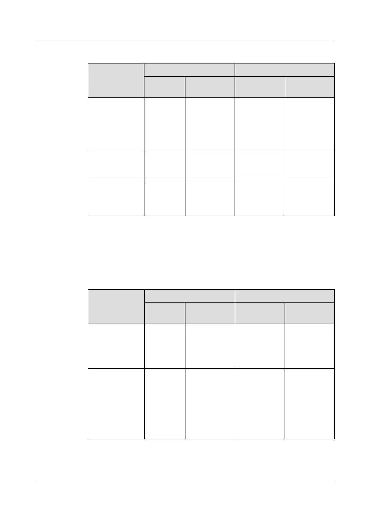
Transmission Cables
Table 7-6 lists the transmission cables that have been installed before delivery. Table 7-7 lists
the transmission cables and CPRI fiber optic cables that need to be installed onsite.
Table 7-6 Transmission cables installed before delivery
Cable
One End The Other End
Connector Installation
Position
Connector Installation
Position
E1/T1 Surge
Protection
Transfer Cable
DB25
connector
INSIDE port on
the UELP in the
BBU
DB26 connector E1/T1 port on
the GTMU,
WMPT, or
UTRP in the
BBU
FE Surge
Protection
Transfer Cable
RJ45
connector
l FE0 port on
the GTMU
or WMPT in
the BBU
l FE0 or FE1
port on the
LMPT in the
BBU
RJ45 connector
FE0 port in the
INSIDE part on
the UFLP in the
BBU
BTS3900C (Ver.C)
Hardware Description 7 BTS3900C Cables
Issue 03 (2013-05-27) Huawei Proprietary and Confidential
Copyright © Huawei Technologies Co., Ltd.
124