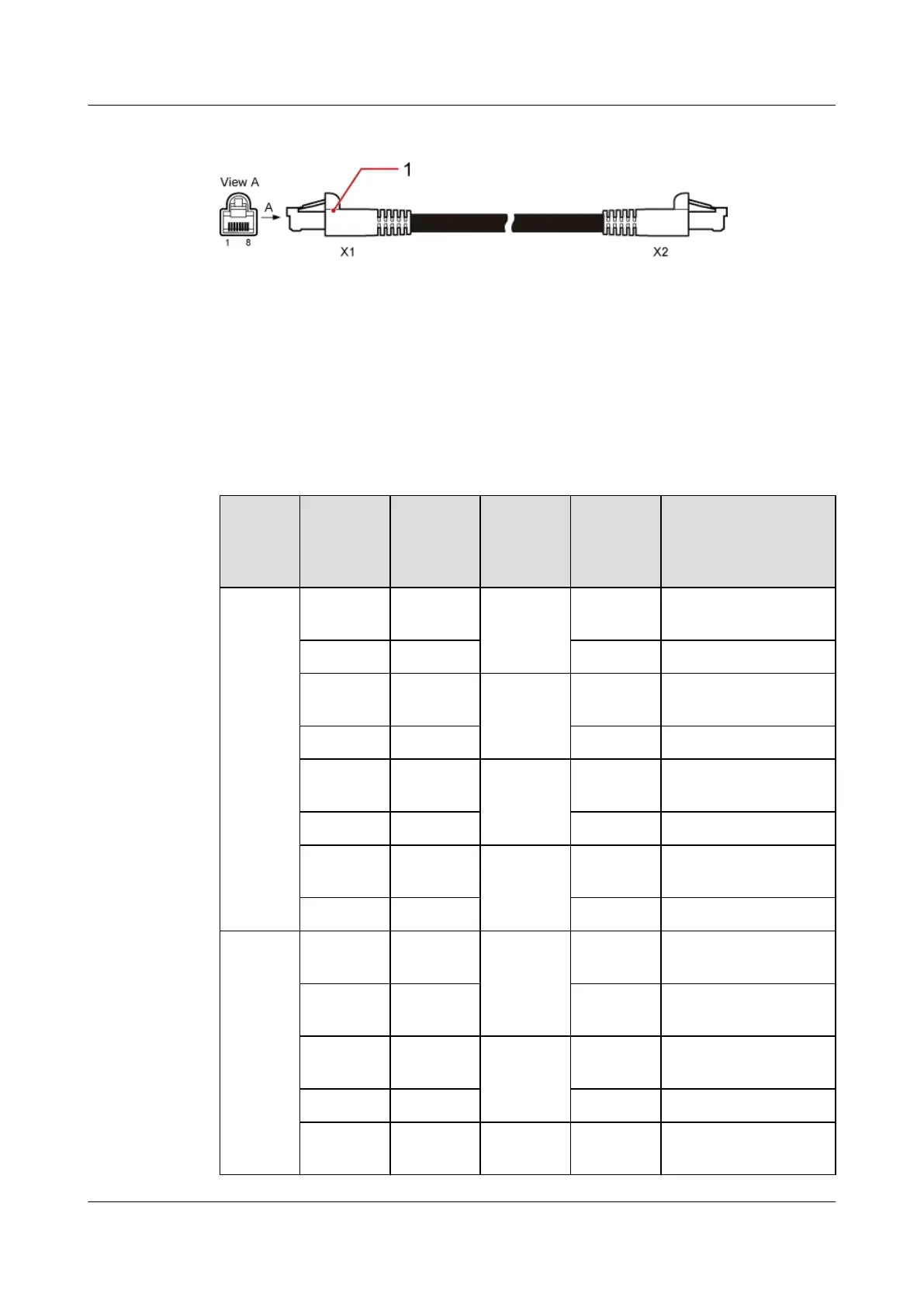
Figure 7-42 BBU alarm cable
(1) RJ45 connector
Pin Assignment
Table 7-38 shows the wire sequence of the BBU alarm cable.
Table 7-38 Pin assignment for the wires of the BBU alarm cable
BBU
Alarm
Port
Pin on the
RJ45
Connecto
r
Wire
Color
Wire
Type
Pin on the
RJ45
Connecto
r
Description
EXT-
ALM1
X1.1 White and
orange
Twisted
pair
X2.1 Boolean input 4+
X1.2 Orange X2.2 Boolean input 4- (GND)
X1.3 White and
green
Twisted
pair
X2.3 Boolean input 5+
X1.6 Green X2.6 Boolean input 5- (GND)
X1.5 White and
blue
Twisted
pair
X2.5 Boolean input 6+
X1.4 Blue X2.4 Boolean input 6- (GND)
X1.7 White and
brown
Twisted
pair
X2.7 Boolean input 7+
X1.8 Brown X2.8 Boolean input 7- (GND)
EXT-
ALM0
X1.1 White and
orange
Twisted
pair
X2.1 Boolean input 0+
X1.2 Orange X2.2 Boolean input 0+
(GND)
X1.3 White and
green
Twisted
pair
X2.3 Boolean input 1+
X1.6 Green X2.6 Boolean input 1- (GND)
X1.5 White and
blue
Twisted
pair
X2.5 Boolean input 2+
BTS3900C (Ver.C)
Hardware Description 7 BTS3900C Cables
Issue 03 (2013-05-27) Huawei Proprietary and Confidential
Copyright © Huawei Technologies Co., Ltd.
168