Figures
Figure 2-1 Position of the ePico3801 on the network of the uBro solution.........................................................2-2
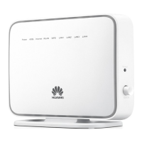
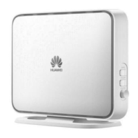
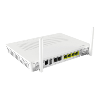
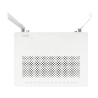
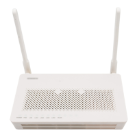
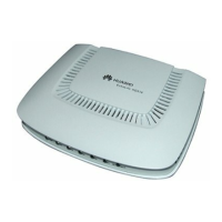
Figure 2-2 Two ePico3801s, one with a built-in antenna and the other with an external antenna.......................2-6
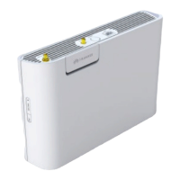
Figure 2-3 Ports and buttons on the panel of the ePico3801................................................................................2-7
Figure 2-4 LEDs of the ePico3801.......................................................................................................................2-8
Figure 2-5 AC/DC power adapter......................................................................................................................2-10
Figure 2-6 PSE...................................................................................................................................................2-11
Figure 2-7 Networking in modem access mode.................................................................................................2-16
Figure 2-8 Networking in LAN access mode.....................................................................................................2-17
Figure 2-9 Typical installation scenarios of the ePico3801...............................................................................2-18
Figure 2-10 Application of the ePico3801 in an SME.......................................................................................2-19
Figure 3-1 Logging in to the WebUI....................................................................................................................3-3
Figure 4-1 Commissioning procedures................................................................................................................4-3
ePico3801
User Guide Figures
Issue 01 (2009–09–23) Huawei Proprietary and Confidential
Copyright © Huawei Technologies Co., Ltd.
iii