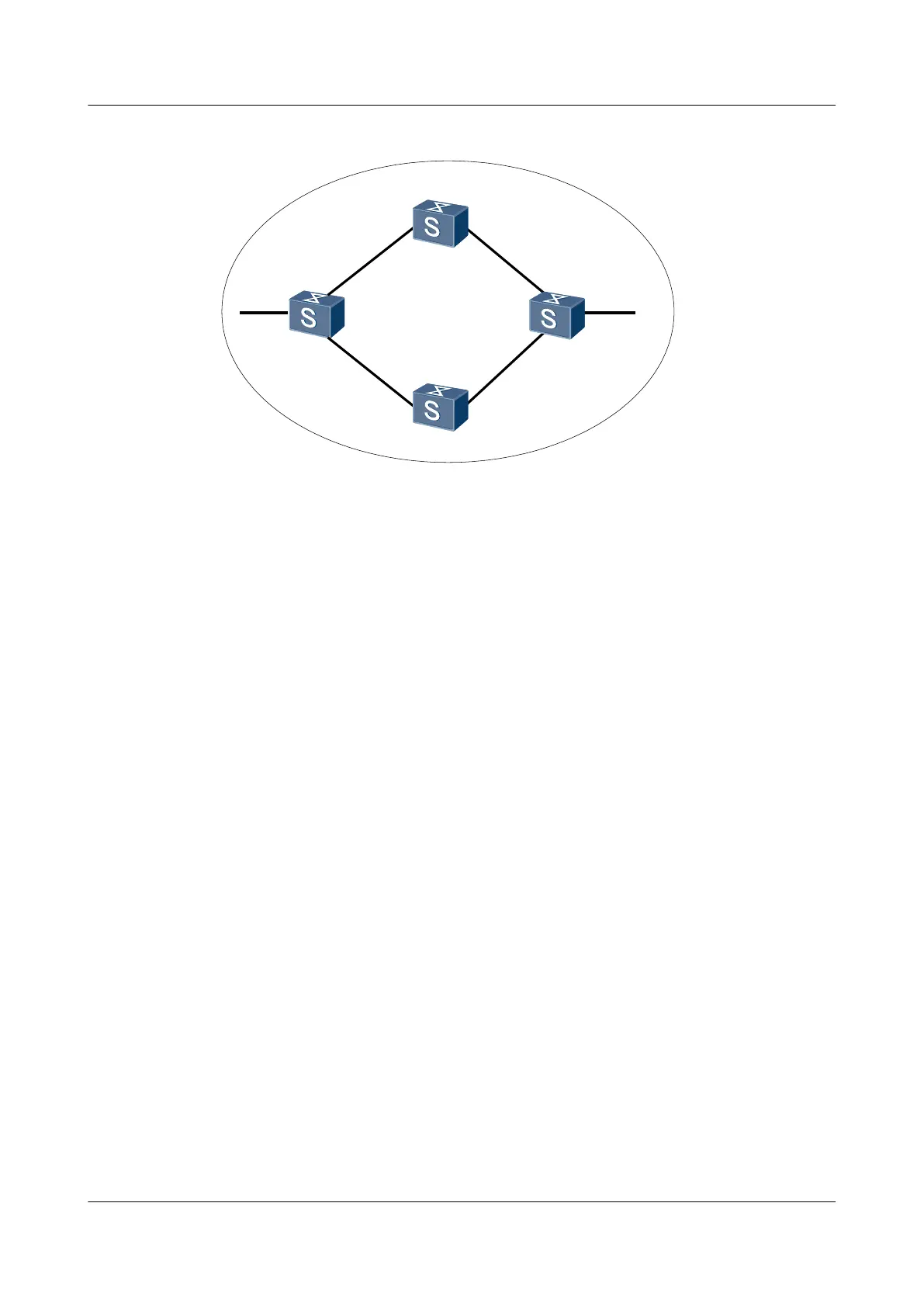
Figure 4-9 Networking diagram for configuring OSPF load balancing
Switch A
Switch B
Switch C
Switch D
XGE 0/0/1
XGE 0/0/1XGE 0/0/1
XGE 0/0/1
XGE 0/0/3
XGE 0/0/2
XGE 0/0/2
XGE 0/0/2
XGE 0/0/2
XGE 0/0/3
Area 0
Device Interface VLANIF Interface IP Address
SwitchA XGE 0/0/1 VLANIF 10 10.1.1.1/24
SwitchA XGE 0/0/2 VLANIF 20 10.1.2.1/24
SwitchA XGE 0/0/3 VLANIF 50 172.16.1.1/24
SwitchB XGE 0/0/1 VLANIF 10 10.1.1.2/24
SwitchB XGE 0/0/2 VLANIF 30 192.168.0.1/24
SwitchC XGE 0/0/1 VLANIF 20 10.1.2.2/24
SwitchC XGE 0/0/2 VLANIF 40 192.168.1.1/24
SwitchD XGE 0/0/1 VLANIF 30 192.168.0.2/24
SwitchD XGE 0/0/2 VLANIF 40 192.168.1.2/24
SwitchD XGE 0/0/3 VLANIF 60 172.17.1.1/24
Configuration Roadmap
The configuration roadmap is as follows:
1. Enable OSPF on each Switch to implement interconnection.
2. Cancel load balancing and check the routing table.
3. (Optional) Set the preferences for equal-cost routes on SwitchA.
Data Preparation
To configure OSPF load balancing, you need the following data:
l The ID of the VLAN to which each interface belongs is shown in Figure 4-9.
l The IP address of each interface is shown in Figure 4-9.
l The router ID of each Switch, the OSPF process ID, and the area to which each interface
belongs are as follows:
S6700 Series Ethernet Switches
Configuration Guide - IP Routing 4 OSPF Configuration
Issue 01 (2012-03-15) Huawei Proprietary and Confidential
Copyright © Huawei Technologies Co., Ltd.
157

 Loading...