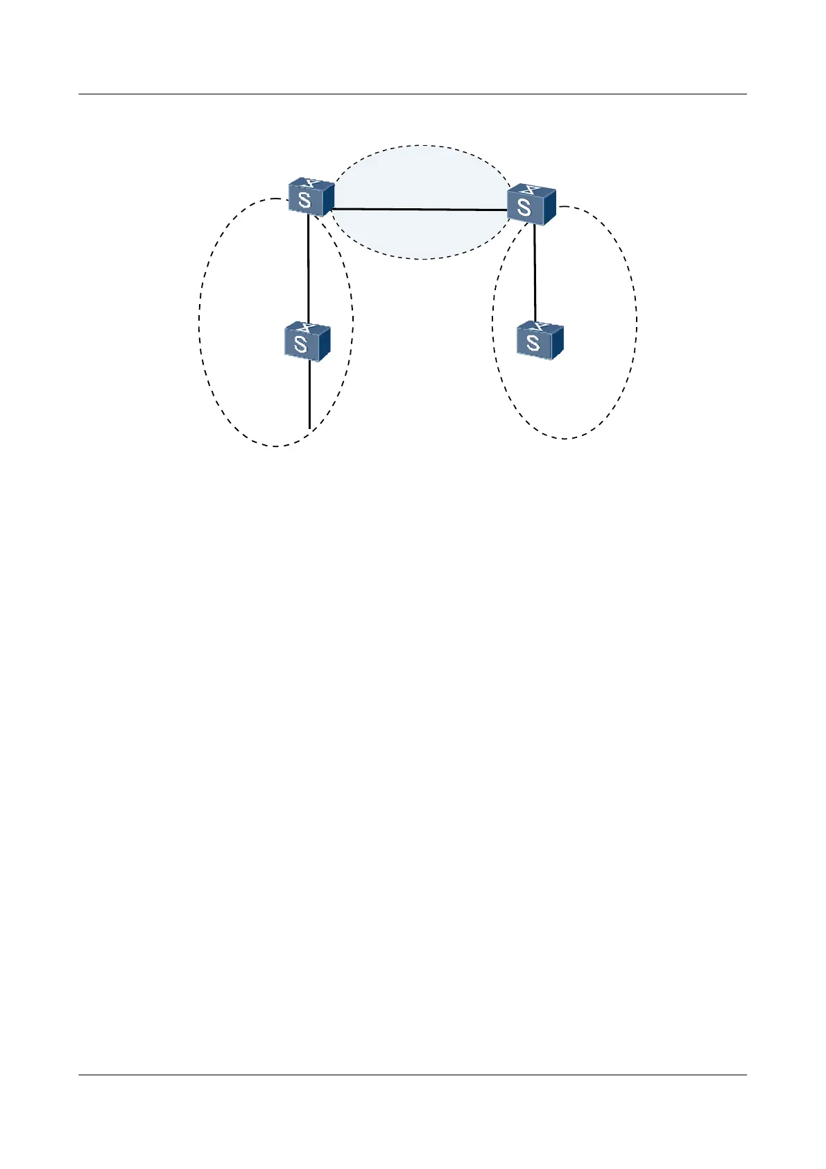
Figure 5-1 Networking diagram for configuring an OSPFv3 area
SwitchA
XGE0/0/1
XGE0/0/1
XGE0/0/2
XGE0/0/1
XGE0/0/2
XGE0/0/3
SwitchD
SwitchB
2000::1/64
VLANIF10
VLANIF30
VLANIF20
VLANIF20
VLANIF40
1002::2/64
VLANIF40
SwitchC
Area 0
Area 1
Area 2
Stub
1001::2/64
1001::1/64
1000::1/64
XGE0/0/2
VLANIF30
1000::2/64
1002::1/64
Device name Interface VLANIF interface IP address
Switch A XGE0/0/1 VLANIF 20 1001::2/64
Switch B XGE0/0/1 VLANIF 20 1001::1/64
Switch B XGE0/0/2 VLANIF 30 1000::1/64
Switch C XGE0/0/2 VLANIF 30 1000::2/64
Switch C XGE0/0/1 VLANIF 40 1002::1/64
Switch D XGE0/0/2 VLANIF 40 1002::2/64
Configuration Roadmap
The configuration roadmap is as follows:
1. Configure IPv6 addresses for interfaces.
2. Enable the basic OSPFv3 functions on each Switch.
3. Configure Area 2 as a stub area by running the stub command on all the Switches in Area
2 and check the OSPFv3 routing table of Switch D.
4. Configure the Area 2 as a totally stub area and check the OSPFv3 routing table of Switch
D.
Data Preparation
To complete the configuration, you need the following data:
l IDs of the VLANs that the interfaces belong to, as shown in Figure 5-1
l Router ID (1.1.1.1) of Switch A and area (Area 1) where Switch A is located
l Router ID (2.2.2.2) of Switch B and areas (Area 0 and Area 1) where Switch B is located
S6700 Series Ethernet Switches
Configuration Guide - IP Routing 5 OSPFv3 Configuration
Issue 01 (2012-03-15) Huawei Proprietary and Confidential
Copyright © Huawei Technologies Co., Ltd.
214

 Loading...