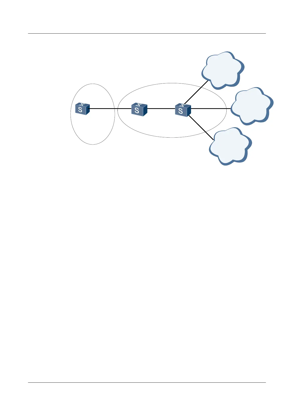
Figure 6-4 Networking diagram for configuring IS-IS route convergence
Switch A
L2
Switch B Switch C
L1/L2 L1
XGE 0/0/1
XGE 0/0/2
XGE 0/0/1
XGE 0/0/1
XGE 0/0/2
XGE 0/0/3
XGE 0/0/4
network 1
172.1.1.0/24
network 2
172.1.2.0/24
network 3
172.1.3.0/24
Area 10
Area 20
Switch Interface VLANIF Interface IP Address
SwitchA XGE 0/0/1 VLANIF 50 172.2.1.1/24
SwitchB XGE 0/0/1 VLANIF 10 172.1.4.2/24
SwitchB XGE 0/0/2 VLANIF 50 172.2.1.2/24
SwitchC XGE 0/0/1 VLANIF 10 172.1.4.1/24
SwitchC XGE 0/0/2 VLANIF 20 172.1.1.1/24
SwitchC XGE 0/0/3 VLANIF 30 172.1.2.1/24
SwitchC XGE 0/0/4 VLANIF 40 172.1.3.1/24
Configuration Roadmap
The configuration roadmap is as follows:
1. Enable basic IS-IS functions on each Switch so that the Switches can be interconnected.
2. Check the IS-IS routing table of SwitchA.
3. Configure route convergence on SwitchB.
Data Preparation
To complete the configuration, you need the following data:
l VLAN ID of each interface, as shown in Figure 6-4
l IP address of each VLANIF interface, as shown in Figure 6-4
l System ID, level, and area ID of each Switch
– SwitchA: The system ID is 0000.0000.0001; the area ID is 20; the level is Level-2.
S6700 Series Ethernet Switches
Configuration Guide - IP Routing 6 IS-IS Configuration
Issue 01 (2012-03-15) Huawei Proprietary and Confidential
Copyright © Huawei Technologies Co., Ltd.
324

 Loading...