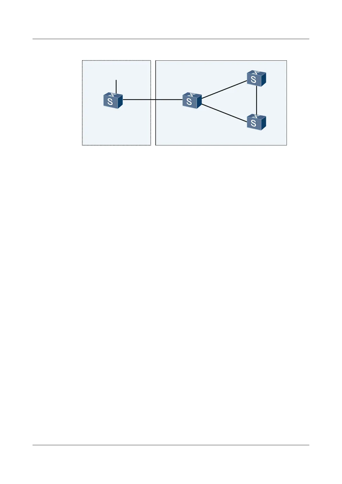
Figure 7-4 Networking diagram for configuring basic BGP functions
XGE0/0/2
XGE0/0/1
Switch A
XGE0/0/1
XGE0/0/2
XGE0/0/3
XGE0/0/1
XGE0/0/2
XGE0/0/1
XGE0/0/2
Switch B
Switch C
Switch D
AS65008 AS65009
Switch Interface VLANIF Interface IP Address
SwitchA XGE 0/0/1 VLANIF 10 200.1.1.2/24
SwitchA XGE 0/0/2 VLANIF 50 8.1.1.1/8
SwitchB XGE 0/0/1 VLANIF 10 200.1.1.1/24
SwitchB XGE 0/0/2 VLANIF 20 9.1.3.1/24
SwitchB XGE 0/0/3 VLANIF 30 9.1.1.1/24
SwitchC XGE 0/0/1 VLANIF 20 9.1.3.2/24
SwitchC XGE 0/0/2 VLANIF 40 9.1.2.1/24
SwitchD XGE 0/0/1 VLANIF 30 9.1.1.2/24
SwitchD XGE 0/0/2 VLANIF 40 9.1.2.2/24
Configuration Roadmap
The configuration roadmap is as follows:
1. Set up IBGP peer relationships between SwitchB, SwitchC and SwitchD.
2. Create an EBGP peer relationship between SwitchA and SwitchB.
3. Advertise routes through the network command on SwitchA and check the routing tables
of SwitchA, SwitchB, and SwitchC.
4. Configure BGP on SwitchB to import direct routes, and check the routing tables of
SwitchA and SwitchC.
Data Preparation
To complete the configuration, you need the following data:
l The VLAN ID of each interface is shown in Figure 7-4.
l The IP address of each VLANIF interface is shown in Figure 7-4.
l The router ID of SwitchA is 1.1.1.1 and the number of the AS where it resides is 65008.
S6700 Series Ethernet Switches
Configuration Guide - IP Routing 7 BGP Configuration
Issue 01 (2012-03-15) Huawei Proprietary and Confidential
Copyright © Huawei Technologies Co., Ltd.
444

 Loading...