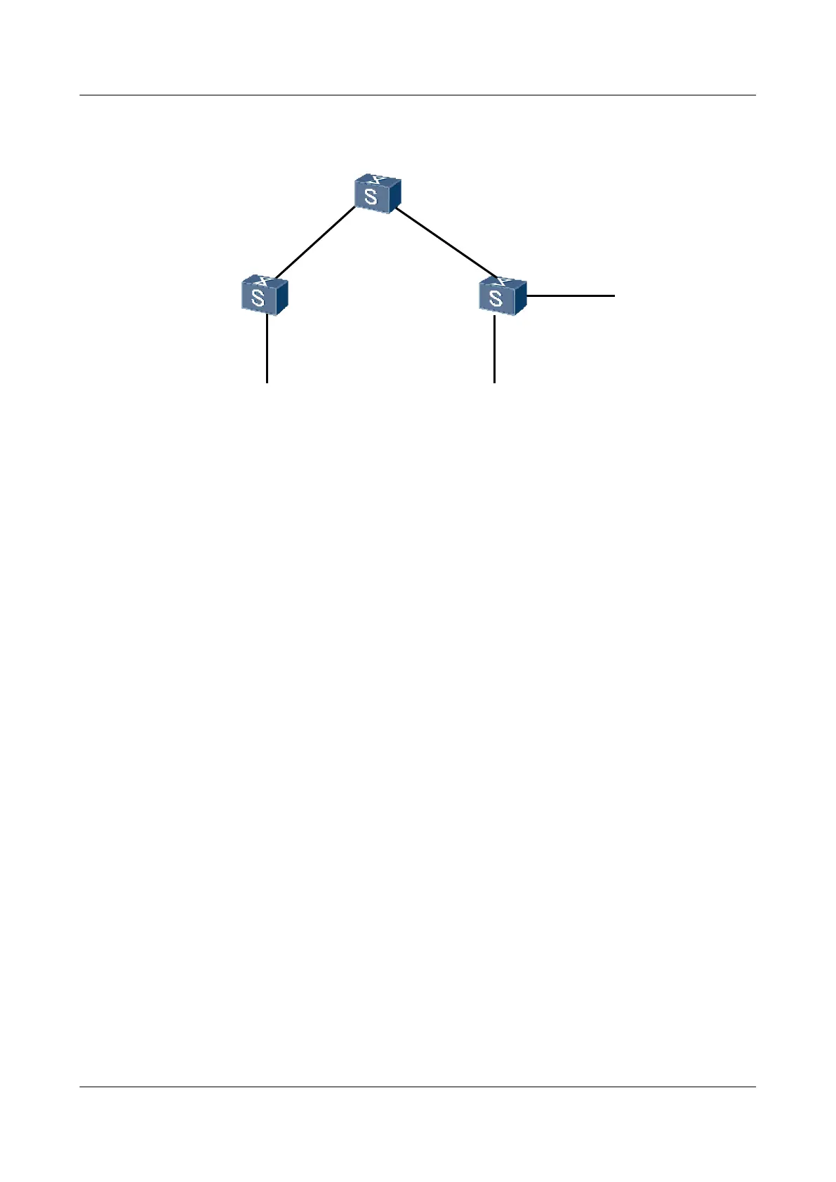
Figure 3-1 Networking diagram for configuring RIPng to filter the received routes
SwitchA
XGE0/0/1
XGE0/0/1 XGE0/0/2
XGE0/0/1
XGE0/0/2
XGE0/0/2
SwitchB
1::1/64
3::1/64
VLANIF10
VLANIF50
VLANIF30
VLANIF20
VLANIF20
VLANIF30
2::1/64
XGE0/0/3
VLANIF40
SwitchC
Device name Interface VLANIF interface IP address
Switch A XGE0/0/2 VLANIF 10 1::1/64
Switch A XGE0/0/1 VLANIF 20 Generated
automatically
Switch B XGE0/0/1 VLANIF 20 Generated
automatically
Switch B XGE0/0/2 VLANIF 30 Generated
automatically
Switch C XGE0/0/1 VLANIF 30 Generated
automatically
Switch C XGE0/0/2 VLANIF 40 2::1/64
Switch C XGE0/0/3 VLANIF 50 3::1/64
Configuration Roadmap
The configuration roadmap is as follows:
1. Enable RIPng on each Switch so that the Switches can communicate with each other.
2. Configure an ACL on Switch B to filter the received routes.
Data Preparation
To complete the configuration, you need the following data:
l IDs of the VLANs that the interfaces belong to, as shown in Figure 3-1
l RIPng1 enabled on each Switch
l ACL6 2000 on Switch B, which rejects the routes from network segment 3::/64
Procedure
Step 1 Add interfaces to VLANs.
S6700 Series Ethernet Switches
Configuration Guide - IP Routing 3 RIPng Configuration
Issue 01 (2012-03-15) Huawei Proprietary and Confidential
Copyright © Huawei Technologies Co., Ltd.
77

 Loading...