PSP8620311
Rev. E
4
Contents
Tables & Figures....................................................Page Number
Table 1-1 Duty Cycle ................................................................................. 6
Table 1-2 Recloser Catalog Number Matrix............................................... 6
Table 2-1 Hardware Torque Specifications ............................................... 9
Table 9-1 Trouble Shooting Guide............................................................ 46
Figure 1-1 Pole/Structure Face Mounting .................................................6
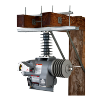
Figure 1-2 Crossarm Mounting .................................................................6
Figure 3-1 Components............................................................................10
Figure 4-1 Packaged NR Hookstick Adapter Kit........................................11
Figure 4-2 NR Hookstick Adapter Kit Components................................... 11
Figure 4-3 NR Hookstick Adapter Positioning for Assembling...................11
Figure 4-4 Clevis Pin Insertion for NR Hookstick Adapter......................... 11
Figure 4-5 Cotter Pin Insertion for NR Hookstick Adapter......................... 11
Figure 4-6 Pole/Structure Face Mounting .................................................12
Figure 4-7 Crossarm Mounting ................................................................ 12
Figure 4-8 Bypass Arrangement .............................................................. 12
Figure 4-9 Program/Installation Tag ........................................................ 13
Figure 4-10 Pole/Structure Mount Assembly Detail ................................... 14
Figure 4-11 Pole/Structure Mount Installation ........................................... 14
Figure 4-12 Recloser in Sling ..................................................................... 14
Figure 4-13 Crossarm Assembly Detail ...................................................... 15
Figure 4-14 Crossarm Mount Installation ................................................... 15
Figure 5-1 Feature Position .......................................................................18
Figure 6-1 Connecting Local Radio ...........................................................19
Figure 6-2 Settings Tab of Programmer Software .................................... 27
Figure 6-3 Real Time Monitoring Tab of Programmer Software .............. 36
Figure 6-4 Events and Data Log Tab of Programmer Software ................ 37
Figure 6-5 Sequence Coordination enabled on four operations
and the SC Lockout option Checked ...................................... 38
Figure 6-6 Sequence Coordination enabled on four operations
and the SC Unchecked ........................................................... 38
Figure 6-7 Time and Security Tab ............................................................ 39
Figure 6-8 Scratchpad Tab ....................................................................... 40
Figure 7-1 Recloser attached to high potential test set ........................... 42
Figure 7-2 Recloser attached to high current test set ............................. 43
Figure 8-1 Battery bayonet in the recloser .............................................. 44
Figure 8-2 Battery bayonet partially removed from recloser ................... 44