Electronic Overspeed Switch EGS 40
EGS40_MANUAL-en_R6(2018-11-07)ID74528.docx
4 Structure and function
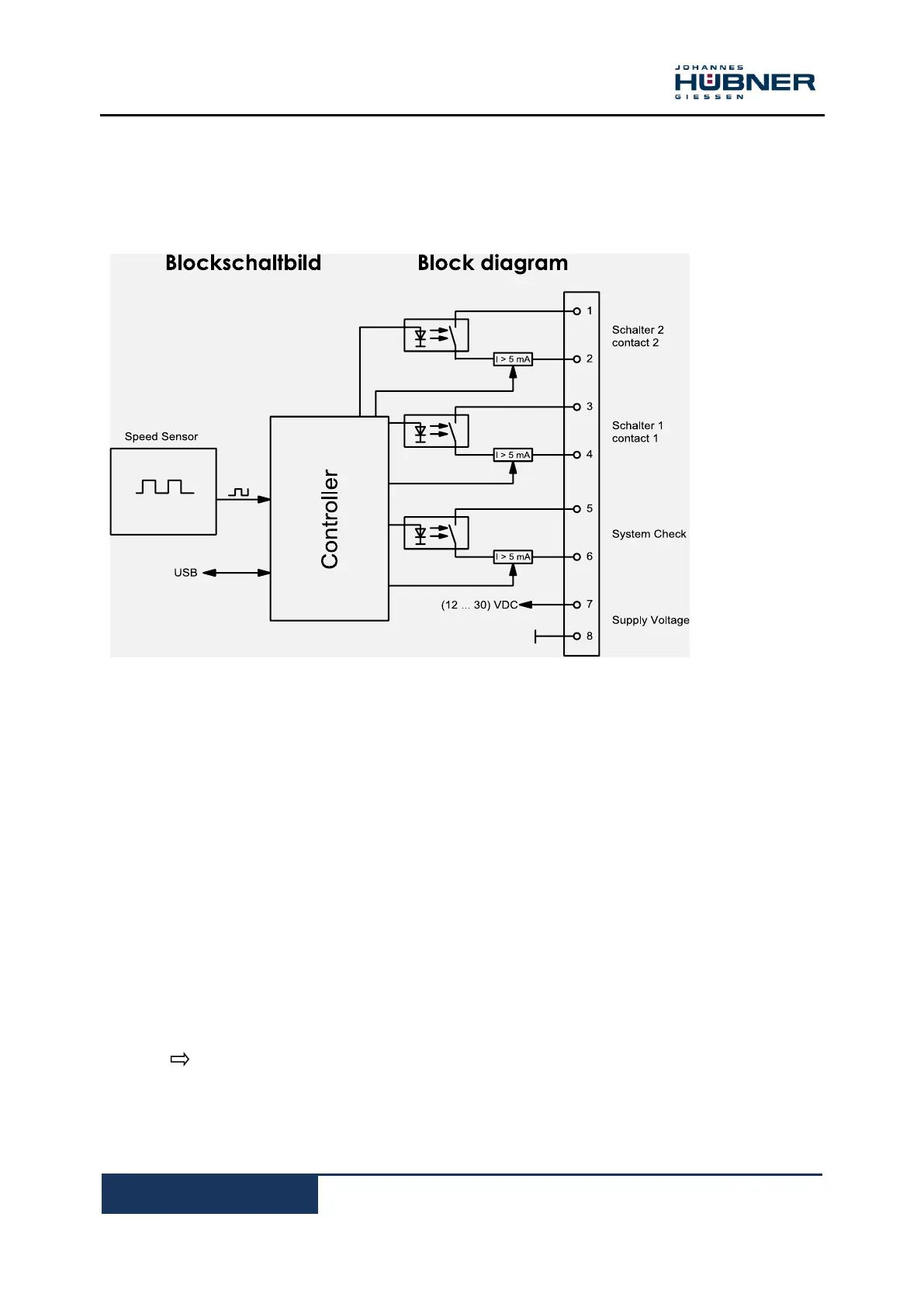
4.1 Block diagram
4.2 Brief description
The integrated speed sensor consists of a pulse disk with optical scanning, and it generates a
speed-proportional frequency. The analysis unit (controller) further processes this frequency.
The actual speed is continuously compared with the programmed limit speeds in the read-only
memory (EEPROM). When a limit value is reached the analysis units triggers the associated
switch.
Analysis unit:
After applying the supply voltage there is a plausibility check and there after the device is ready for
operation.
Read-only memory:
The following data are stored in the programmable EEPROM read only memory:
The switching points / limit values for the switching speeds.
The switching performance (hysteresis, switching delay).
Date and time the last switching speed was programmed, with user ID.
A 8-digit user-defined device ID.
The device password.
(Details: Chapter 7 Programming instruction)
The programmed data are saved with the appropriate checksum and verified at each device start.
Serial interface:
The device is programmed via the RS232-interface using the supplied programming cable and the
EGS
®
40-Pro software.
 Loading...