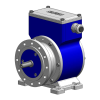
Electronic Overspeed Switch EGS 40
EGS40_MANUAL-en_R6(2018-11-07)ID74528.docx
Directory
1 General ............................................................................................................................ 5
1.1 Information about the assembly instruction ................................................................................ 5
1.2 Scope of delivery ........................................................................................................................ 5
1.3 Explanation of symbols ............................................................................................................... 5
1.4 Disclaimer ................................................................................................................................... 6
1.5 Copyright..................................................................................................................................... 6
1.6 Guarantee terms ......................................................................................................................... 6
1.7 Customer service ........................................................................................................................ 6
2 Safety ............................................................................................................................... 6
2.1 Responsibility of the owner ......................................................................................................... 6
2.2 Intended use ............................................................................................................................... 6
2.3 Improper use ............................................................................................................................... 7
2.4 Personal protective equipment ................................................................................................... 7
2.5 Special dangers .......................................................................................................................... 7
2.5.1 Electrical current .................................................................................................... 7
2.5.2 Rotating shafts ...................................................................................................... 7
2.5.3 Safeguarding against restart .................................................................................. 7
3 Technical data ................................................................................................................. 8
3.1 Type plates ................................................................................................................................. 8
3.2 Type key ..................................................................................................................................... 9
3.2.1 Mechanical Data ...................................................................................................10
3.3 Connected loads and values .................................................................................................... 10
3.3.1 Dimensions, connected loads, environment .........................................................10
3.3.2 Electrical Outputs .................................................................................................10
3.3.3 Speeds .................................................................................................................11
3.3.4 Switching performance .........................................................................................11
3.3.5 Degree of protection .............................................................................................12
3.3.6 Outputs .................................................................................................................13
3.3.7 incremental encoder type FG with integrated EGS® 4 technology (option S) ......13
4 Structure and function ..................................................................................................14
4.1 Block diagram ........................................................................................................................... 14
4.2 Brief description ........................................................................................................................ 14
5 Transport, packaging, and storage ..............................................................................15
5.1 Instructions for transport ........................................................................................................... 15
5.2 Symbols on the packaging........................................................................................................ 15
5.3 Transport inspection ................................................................................................................. 16
5.4 Packaging ................................................................................................................................. 16
6 Installation and commissioning ....................................................................................16
6.1 Versions .................................................................................................................................... 16
6.2 Installation tasks ....................................................................................................................... 17
6.2.1 Device execution for flange design (B5) or foot design (B35) ...............................17

 Loading...