Electronic Overspeed Switch EGS 40
EGS40_MANUAL-en_R6(2018-11-07)ID74528.docx
6.2 Installation tasks
6.2.1 Device execution for flange design (B5) or foot design (B35)
1. Use a play-free coupling.
2. Ensure precise catered attachment, particularly with foot design B35 (double coupling HKD5 is
recommended).
3. Fix device in place via flange or foot.
4. Make the connections in the terminal box ( Appendix, Connection diagrams).
6.2.2 Assembly instruction no. 54690 for coupling type HK….5
1. Select coupling bore with G7 fit (tolerance field is above the zero line).
2. Push the coupling onto the shaft with easy movement. Finishes ream the associated bore if
necessary.
3. Secure the hub against axial offset with M4 radial set screw (with tip). The set screw presses
on the feather key so that the shaft is not damaged.
Consider the permissible compliance:
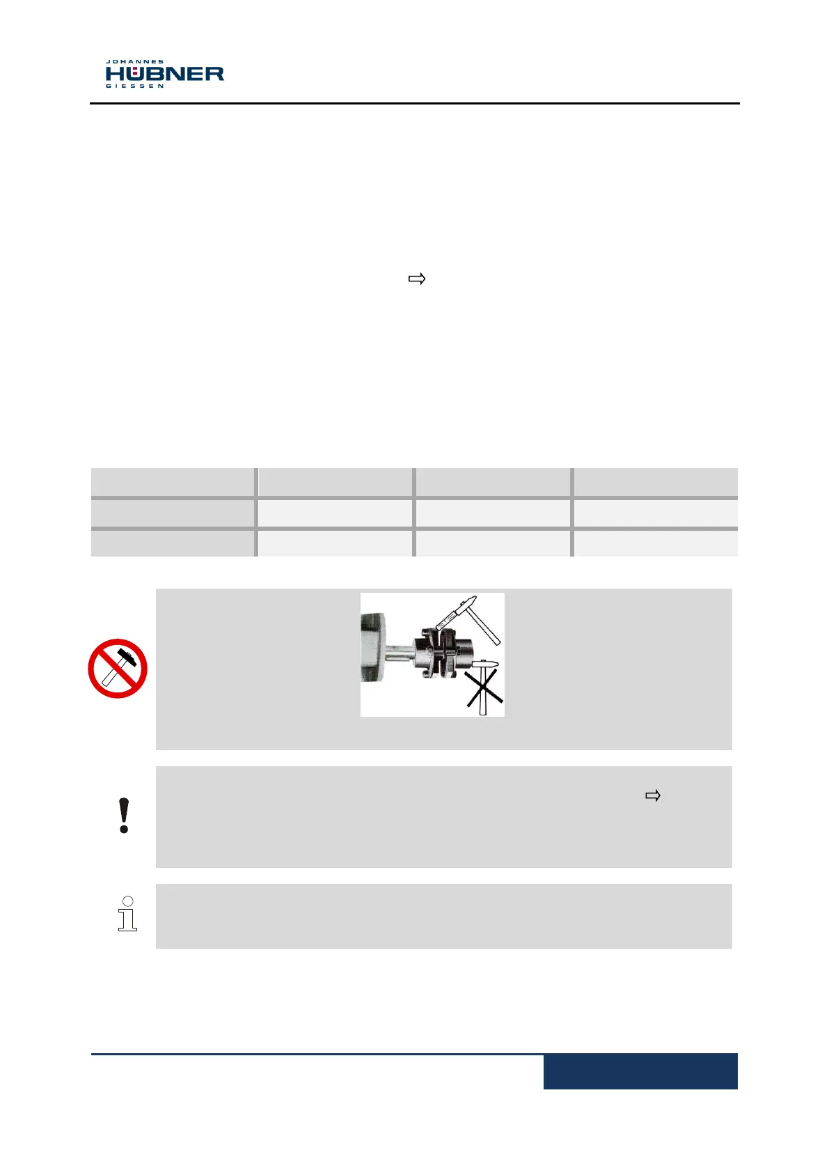
CAUTION!
Danger of damage or breakage if the coupling is not improperly handled ( Fig. 1).
No hard impacts on coupling and shaft
Do not deform the coupling
Do not exceed compliance as specified
Precisely align coupled machines
NOTE
The more precise the attachment,
the longer the service life of the coupling and bearing encoder
and the lower the degree of influence on encoder signal quality (harmonics)
Additional instructions on couplings are provided in the current Hubner Giessen catalog "Torsion-
resistant stiff couplings for encoders".
 Loading...