2.7
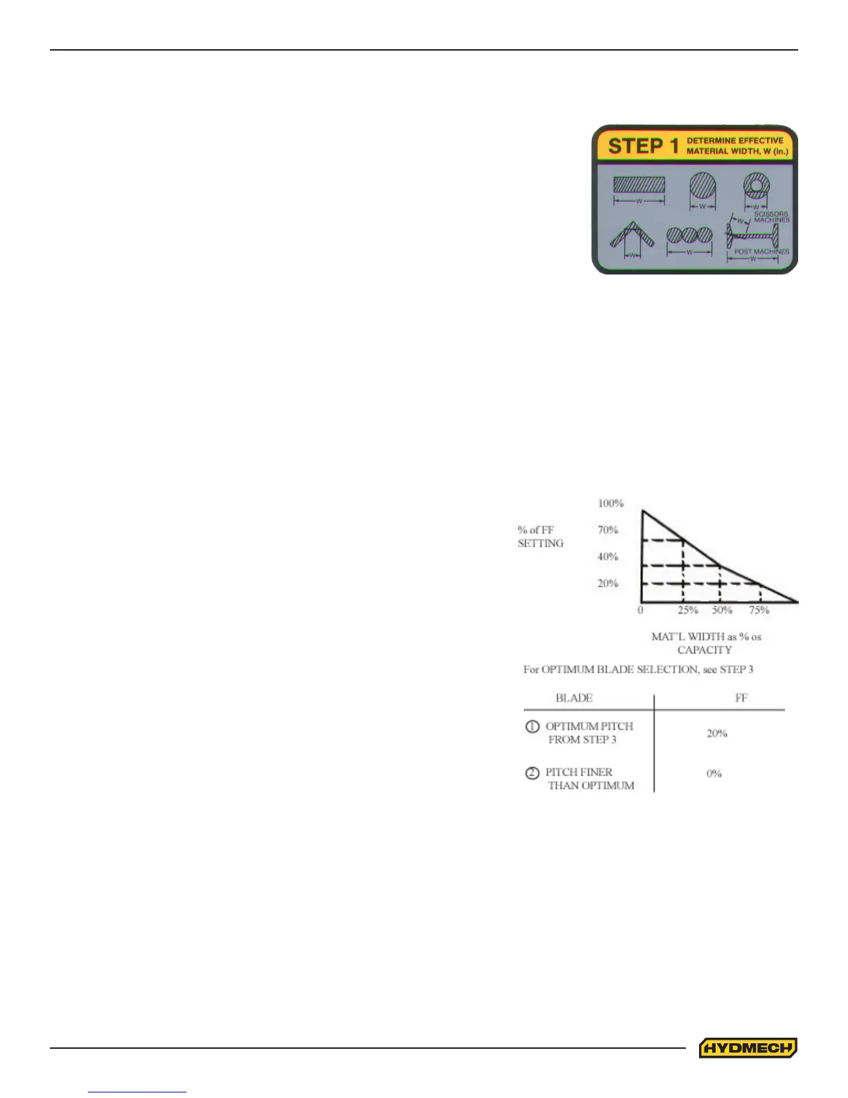
STEP 2, SET FEED FORCE LIMIT
The Feed Force Limit is the maximum amount of force with which the head is allowed to push the blade into the work-
piece. FEED FORCE LIMIT should be set with the head in the down mode, according to the label.
CUTTING SOLIDS
For cutting solids, the wider the section, the less FF should be set, to avoid
blade overloading. See the graph.
EXAMPLE: When cutting a solid which is 1/2 of machine capacity using
the graph, locate 50% on the horizontal line and travel upwards to the plot-
ted line and then travel directly across to the vertical FF Setting line. The
point that you have arrived at shows a setting of 40% for a piece 50% of
capacity.
CUTTING STRUCTURALS
A reduced Feed Force Setting is used when cutting structurals:
For structurals, a blade ner than Optimum can be used for more ecient
cutting.
If a ner than optimum blade is going to be used, Feed Force Setting
should be reduced even further.
CHART EXAMPLE #1
We will use the parameters chart to set up the saw for cutting 8” (200mm) Diameter #1045 Carbon Steel.
STEP 1, DETERMINE EFFECTIVE MATERIAL WIDTH - W ( inches ) or (mm)
Eective material width, W (in.) for most common shapes of materials, is the widest
solid part of the material to be in contact with blade during cutting. For simple shapes,
as illustrated on the chart, this can be directly measured. For bundles of tubes and
structurals, measuring the eective width is dicult. Eective width is 60% to 75% of the
actual material width.
NOTES:
1) Both eective material width and guide arm width are used in setting the saw.
2) Guide arm width is the distance between the guide arms and is used in STEP 2.
3) Eective material width, as determined here in STEP 1, can be thought of as the average width of material “seen” by
each tooth, and it is used in STEPS 3 and 4. In Example #1, for an 8” (200 mm) diameter solid, Eective Material Width is
8” (200mm).