OPERATION
HySpeed HT2000LHF Instruction Manual 4-25
Shield Arc Approx.
Material
Plasma Gas Flow Rate %
Gas (Air) Torch-to-work Initial Torch Voltage Motion
Thickness Preflow Cutflow Pressure Distance Piercing Height Setting Travel Speed Delay Time
(inches) (mm) (N
2
%) (N
2
%) (psi) (inches) (mm) (inches) (mm) (volts) (ipm) (mm/min.) (sec)
Shield Arc Approx.
Material
Plasma Gas Flow Rate %
Gas (Air) Torch-to-work Initial Torch Voltage Motion
Thickness Preflow Cutflow Pressure Distance Piercing Height Setting Travel Speed Delay Time
(inches) (mm) (N
2
%) (N
2
%) (psi) (inches) (mm) (inches) (mm) (volts) (ipm) (mm/min.) (sec)
3/16 5 50 60 60 1/8 3 1/4 6 130 180 4570 0.5
1/4 6 (66.4 (79.6 (270 1/8 3 1/4 6 135 160 4060 1.0
3/8 10 SCFH) SCFH) SCFH) 1/8 3 1/4 6 135 120 3050 1.5
1/2 12 1/8 3 1/4 6 140 80 2030 2.0
5/8 15 .157 4 .314 8 140 70 1780 2.0
3/4 20 3/16 5 3/8 10 150 50 1270 2.5
7/8 22 1/4 6 1/2 12 160 35 890 2.5
1 25 1/4 6 165 25 635
1-1/4 32 ` 1/4 6 175 20 510
1-1/2 38 1/4 6 185 10 250
Aluminum
200 amps • N
2
Plasma / Air Shield
This gas combination is used when cut edge quality is less important. Electrode life is extended when this
combination is used.
Notes: Set plasma gas inlet pressure to 120 psi (8.3 bar)
Set shield gas inlet pressure to 90 psi (6.2 bar)
Production cutting above 7/8" (22 mm) not recommended
Above Water
3/16 5 50 60 70 1/8 3 1/4 6 135 170 4350 0.5
1/4 6 (66.4 (79.6 (280 1/8 3 1/4 6 140 140 3650 1.0
3/8 10 SCFH) SCFH) SCFH) 1/8 3 1/4 6 140 100 2600 1.5
1/2 12 1/8 3 1/4 6 145 65 1620 2.0
5/8 15 .157 4 .314 8 145 55 1350 2.5
3/4 20 3/16 5 3/8 10 155 35 890 3.0
7/8 22 1/4 6 1/2 12 165 25 620 3.0
3" Under Water
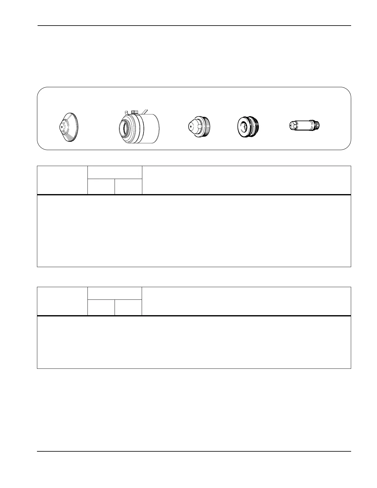
020424
Shield
120837
Retaining cap
020608
Nozzle
020607
Swirl ring
020415
Electrode
7
 Loading...