Do you have a question about the Hypertherm XPR300 and is the answer not in the manual?
Overview of EMC compliance for Hypertherm CE-marked equipment and installation guidelines.
User responsibility for installation and resolving electromagnetic disturbances.
Assessing potential electromagnetic problems in the surrounding area before installation.
Techniques to reduce electromagnetic emissions, including mains supply and cable management.
Routine maintenance requirements to maintain electromagnetic compatibility.
Guidelines for cutting cables and equipotential bonding to manage interference.
Practices for earthing the workpiece to reduce emissions and manage safety.
Selective screening and shielding of cables and equipment to alleviate interference.
Importance of using factory-recommended Hypertherm parts for warranty.
Hypertherm's warranty for products being free from defects in materials and workmanship.
Hypertherm's obligation to defend against patent infringement claims.
Exclusion of incidental, consequential, punitive, or exemplary damages.
National and local codes governing plumbing and electrical installation take precedence.
Definitions of key terms used in the XPR cutting system.
Description of the XPR cutting system's general features and components.
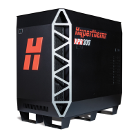
Details on the plasma power supply, including dimensions and weight.
Table of general specifications for the plasma power supply.
Table detailing part numbers and specifications for plasma power supplies.
Part numbers and dimensions for Core, VWI, and OptiMix gas connect consoles.
Dimensions and specifications for the TorchConnect console.
Details on torch dimensions, weight, and general specifications.
List of critical raw materials used in Hypertherm components.
Explanation of safety and EMC marks found on the product.
Explanation of standard IEC symbols used on the equipment.
List of related manuals and documentation for the XPR system.
Requirements and safety guidelines for operating the cutting system.
Requirements and safety guidelines for performing service and maintenance.
Guidelines for electrical system design, installation, and conformity.
Details on general input power requirements and specific cord/switch needs.
Specifications for process gases, quality, pressure, and flow rates.
Instructions and safety precautions for plumbing supply gases.
Guidelines for selecting and installing gas regulators for optimal performance.
Specifications for water quality, pressure, and flow rate for shield water.
Essential checks and preparations before starting system installation.
A checklist for ensuring all system requirements are met before installation.
Requirements for electrical, process gas, and plumbing systems.
Specifications and requirements for using water as a shield fluid.
Guidelines for positioning system components for optimal performance.
Requirements for length, bend radius, and installation of hoses, cables, and leads.
Detailed procedures for grounding system components to ensure safety and EMI control.
Step-by-step instructions for connecting system components.
Critical safety warnings and precautions before and during installation.
Instructions for connecting the cutting system via EtherCAT.
Instructions for connecting via serial RS-422 and discrete methods.
Instructions for connecting via wireless with the XPR web interface.
Procedure for installing the VDC3 board for AVC systems.
Detailed steps for connecting the VDC3 board to the system.
Steps for connecting to the XPR web interface for system monitoring and control.
Instructions for connecting the system in Access Point (AP) mode.
Instructions for connecting the system to a local network.
Procedure to completely disable the wireless connection on the system.
Description of elements and status indicators on the XPR web interface.
Information on the cutting system's coolant reservoir capacity and requirements.
Step-by-step instructions for filling the coolant reservoir.
Key topics covered in the operation section of the manual.
Description of system controls, CNC interface, and wireless device indicators.
Flowcharts illustrating the states of operation for the XPR cutting system.
Guidance on selecting torch positions and process settings for optimal cutting.
Techniques and considerations for performing bevel cuts with the torch.
Details on processes developed for cutting A36 mild steel.
Information on special cutting processes like underwater cutting.
Guidance on using process IDs to access optimal settings.
Recommendations for selecting and installing consumable parts.
Factors affecting cut quality, including dross and general recommendations.
Best practices and recommendations for achieving optimal piercing results.
Tips and settings to maximize the lifespan of consumable parts.
Importance of following maintenance procedures for system performance and life.
Daily tasks required before system operation for inspection.
Safety procedures for removing power before maintenance.
Procedure to examine gas regulators for proper operation.
Inspection of hoses, cables, and leads for damage or wear.
Inspection of consumables, torch, and receptacle for wear and damage.
Guidelines for identifying emitter wear on electrodes.
Procedures for maintaining the coolant system, including level and condition.
Instructions for replacing the coolant and flushing the system.
Information on diagnosing and troubleshooting system performance issues.
Essential safety guidelines to follow during diagnostic and troubleshooting procedures.
Basic inspection steps to identify obvious problems before detailed troubleshooting.
Procedure for examining printed circuit boards for issues.
Steps to measure line voltage between terminals for troubleshooting.
Explanation of diagnostic codes and how to interpret them.
Troubleshooting steps for low shield water pressure errors.
Troubleshooting steps for low coolant flow errors.
Troubleshooting procedures for over-temperature conditions in system components.
Troubleshooting steps for current sensor diagnostic codes.
Troubleshooting for low inlet pressure issues with H2, Ar, N2, and H2O gases.
Procedure for performing a gas leak test on VWI and OptiMix systems.
List of part numbers and voltage specifications for plasma power supplies.
Part numbers and descriptions for the exterior panels of the power supply unit.
List of fans used in the system, including part numbers and specifications.
Part numbers and descriptions for components of the coolant system.
List of part numbers for Core, VWI, and OptiMix gas connect consoles.
List of part numbers for the Torch Connect console.
Part numbers for components of the torch assembly.
List of consumable starter kits for various applications.
Part numbers for EtherCAT and Discrete CNC interface cables.
Part numbers for work leads connecting the power supply to the cutting table.
Part numbers for torch leads and bevel torch leads.
Part numbers and lengths for oxygen, nitrogen, argon, and air hoses.
Kits available for filter, torch rebuild, shield-fluid, and electronics maintenance.
List and explanation of standard symbols used in wiring diagrams.
Common symbols representing torch components in diagrams.
Information on active (ON) and inactive (OFF) valves during system operation.
| Cutting Current | 300 A |
|---|---|
| Duty Cycle | 100% at 300 A |
| Technology | X-Definition Plasma |
| Gas Supply | Oxygen, Nitrogen, Air |
| Cutting Capacity (Mild Steel) | 38 mm (1.5 in) |
| Severance Capacity (Mild Steel) | 75 mm (3 in) |
| Pierce Capacity (Mild Steel) | 50 mm (2 in) |
| Input Voltage | 200–480 V, 3-PH, 50/60 Hz |


