EasyManuals Logo

Hypertherm XPR300 User Manual

Hypertherm XPR300
438 pages
To Next Page IconTo Next Page
To Previous Page IconTo Previous Page
Page #137 background imageLoading...
Page #137 background image
Installation
3
XPR300 Instruction Manual 809480 137
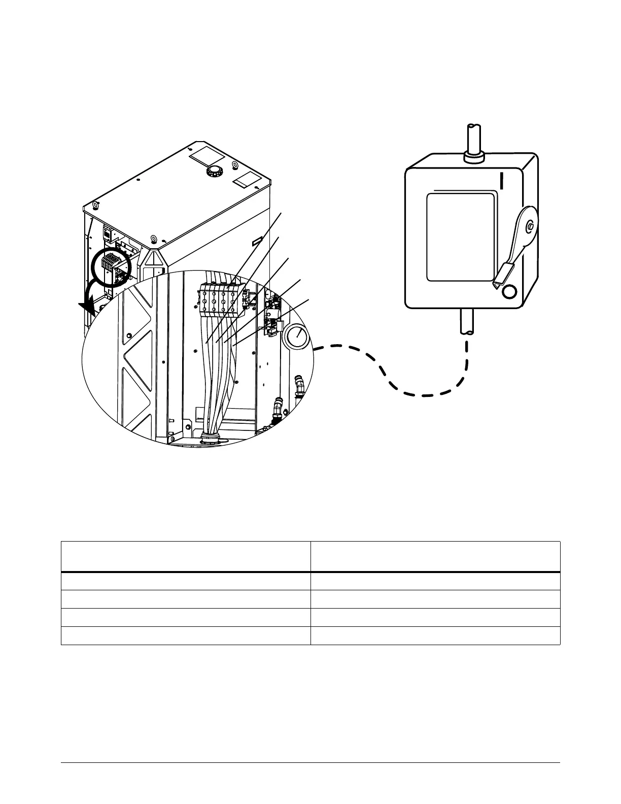
b. Connect the W, V, and U leads from the main power cord to the corresponding TB1
terminals.
Figure 37 Connect the main power cord to the plasma power supply
3. Follow national and local electrical codes to connect the W, V, and U power leads from the main
power cord to the line-disconnect switch (Table 22).
Table 22 Color codes for main power cord wires
U
V
W
GND (PE)
TB1
Wire color codes for North America
Wire color codes for Europe, Asia, and most
locations outside of North America
U = Black U = Black
V = White V = Blue
W = Red W = Brown
PE (earth ground) = Green/yellow PE (earth ground) = Green/yellow

Table of Contents

Other manuals for Hypertherm XPR300

Questions and Answers:

Question and Answer IconNeed help?

Do you have a question about the Hypertherm XPR300 and is the answer not in the manual?

Hypertherm XPR300 Specifications

General IconGeneral
Cutting Current300 A
Duty Cycle100% at 300 A
TechnologyX-Definition Plasma
Gas SupplyOxygen, Nitrogen, Air
Cutting Capacity (Mild Steel)38 mm (1.5 in)
Severance Capacity (Mild Steel)75 mm (3 in)
Pierce Capacity (Mild Steel)50 mm (2 in)
Input Voltage200–480 V, 3-PH, 50/60 Hz

Related product manuals