MAINTENANCE
HySpeed HT2000LHF Instruction Manual 5-5
6
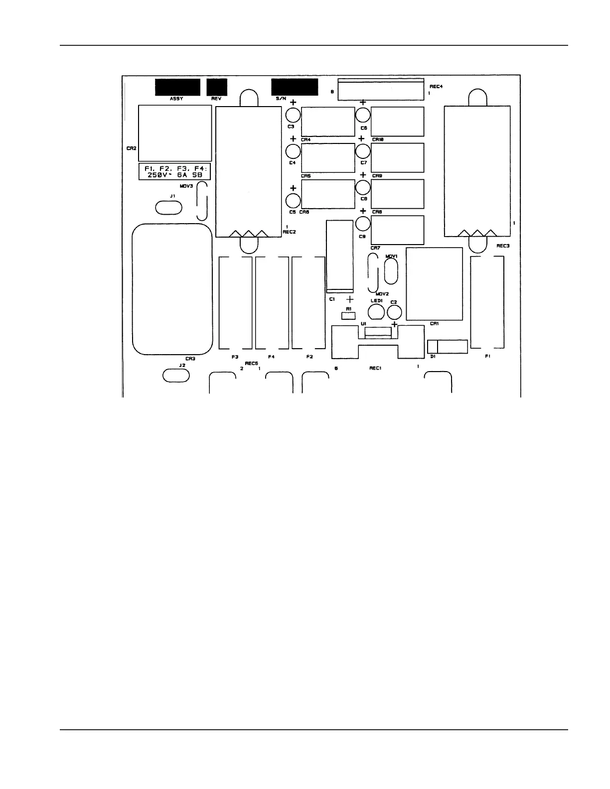
Figure 5-3 Power Distribution Board PCB1
6. Measure the voltage at Power Distribution Board PCB1. Refer to Figure 5-3 for detail of PCB1. Look on the
board for fuses F1-F4. Measurements between each fuse and chassis ground should be as follows:
F1: 24VAC
F2: 120VAC
F3: 240VAC
F4: 120VAC
If voltages are not present, or incorrect at one or more of these points, disconnect the power and troubleshoot
PCB1 fuses and associated pins, connectors and wiring between power distribution board connector REC1 and
transformer secondary T1. Refer to Section 6 for location of T1.
Also, check the main power circuit breaker CB1 and associated wiring and connections between T1 and points L1
and L2.
Repair and/or replace defective component(s) if necessary.
F2F4F3 F1
 Loading...