Lift Pump and Motor 1900 SRM 964
Lift Pump and Motor
GENERAL
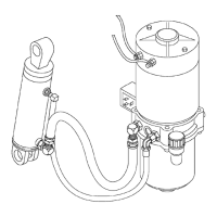
The lift pump and motor assembly consist of:
• Electric Motor
• Lift Pump
• Lowering Valve
• Relief Valve
• Check Valve
• Reservoir
• Inlet Tube and Strainer
• Breather/Filler Cap
The lift pump and motor assemblies are mechani-
cally joined together as a compact unit, combining
the reservoir, pump, valves, and motor. The lift pump
is located inside the hydraulic reservoir and coupled
to the motor by an adapter plate, coupling, and four
capscrews.
Lift pump and motor assembly servicing is best per-
formed by removing the unit from the truck to a clean
work area.
NOTE: It is not necessary to remove the complete
lift pump and motor assembly to remove the reser-
voir. When removing only the reservoir, see Remove
Reservoir.
REMOVE
Lift Pump and Motor Assembly
WARNING
Always wear
the proper protective equipment
including e
ye protection and petroleum-resis-
tant glove
s when handling hydraulic oil. Thor-
oughly was
h oil from exposed areas of skin as
soon as pos
sible.
Completel
y lower forks to relieve hydraulic
pressure b
efore disassembling any part of
the lift pu
mp or disconnecting any hydraulic
hoses.
CAUTION
Make certain the hydraulic cylinder rod is fully
retracted.
Protect the hydraulic system from dirt and
contaminants when servicing the hydraulic
system.
1. Move the lift truck to a safe and level area.
2. Lower the forks completely to relieve pressure
from the hydraulic system.
3. Turn the key switch to the OFF position and dis-
connect battery.
4. Block load wheels to prevent lift truck from
moving. Refer to the section Periodic Mainte-
nance 8000 SRM 919, Periodic Maintenance
8000 SRM 1032, Periodic Maintenance 8000
SRM 1368, or Periodic Maintenance 8000
SRM 1298 - How to Put A Lift Truck on Blocks.
5. Remove the drive unit compartment covers. See
Drive Unit Compartment Covers.
6. Discharge the capacitor. See Special Precau-
tions.
7. Tag and disconnect all power wires and control
wires to the lift pump and motor assembly.
8. Disconnect the hydraulic hoses.
WARNING
Batteries are heavy and can cause personal in-
jury. Use care to avoid injury. DO NOT put
hands, arms, feet, and/or legs between the bat-
tery and a solid object. Make sure the capacity
of the crane and spreader bar is greater than
the weight of the battery. The weight of the
battery is normally shown on the battery case.
The maximum battery weight is shown on the
lift truck nameplate. The spreader bar must
NOT be made of metal or it must have insulated
straps.
9. If necessary, remove the battery. Use a spreader
bar and an overhead lifting device (crane) to re-
move the battery. DO NOT let the battery move
from side to side. Make sure the battery cables
have clearance. See Figure 9.
NOTE: On B60Z, B60Z
AC
,C60Z,C60Z
AC
,andW60Z
lift trucks, it is recommended to connect a piece of
string/rope to the power wires to help guide the wires
back to the controller when reinstalling the lift pump
and motor assembly.
10. Loosen and remove the three capscrews and lock-
washers retaining the lift pump and motor as-
sembly to the frame. Support the lift pump and
motor assembly as the capscrews are being re-
moved. Remove lift pump and motor assembly.
10