1900 SRM 964 Valve Repair
Model Location 1 Location 2 Location 3 Location 4
B60Z, B60Z
AC
, C60Z, C60Z
AC
,and
W60Z
26 N•m
(19 lbf ft)
26 N•m
(19 lbf ft)
N/A
26 N•m
(19 lbf ft)
B80Z, B80Z
AC
, C80Z, C80Z
AC
,
W65Z, and W80Z
26 N•m
(19 lbf ft)
39 N•m
(29 lbf ft)
10 N•m
(7 lbf ft)
N/A
NOTE: Apply Loctite
®
242 to all locations shown during assembly.
CAUTION
Never operate the pump without the proper
amount of oil in the hydraulic system. The
operation of the hydraulic pump with low oil
levels will damage the pump.
5.
Remove breather/filler cap and fill the hydraulic
reservoir to proper level. See Hydraulic Reser-
voir, Table 1.
6. Install breather/filler cap.
7. If removed, install the battery.
8. Remove blocks from wheels.
9. Connect the battery and turn the key switch to
the ON position.
10. Operate the hydraulic functions several times to
purge air from the hydraulic circuit.
WARNING
Never check for leaks by putting hands on
hydraulic lines or components under pressure.
Hydraulic oil under pressure can be injected
into the skin.
11. Test lift truck by lifting and lowering a load sev-
eral times. Check for leaks.
12. Recheck hydraulic oil level in reservoir, and fill
to proper level if needed. Hydraulic Reservoir,
Table 1.
13. Install drive unit compartment covers. See Drive
Unit Compartment Covers.
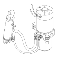
Valve Repair
LOWERING VALVE
Remove
1. Move lift truck to a safe and level area.
2. Lower the forks completely to relieve pressure
from the hydraulic system.
3. Turn the key switch to the OFF position and dis-
connect battery.
4. Block load wheels to prevent lift truck from mov-
ing. See the section Periodic Maintenance
8000 SRM 919, Periodic Maintenance 8000
SRM 1032, Periodic Maintenance 8000 SRM
1368, or Periodic Maintenance 8000 SRM
1298 - How to Put A Lift Truck on Blocks.
5. Remove the drive unit compartment covers. See
Drive Unit Compartment Covers.
6. Discharge the capacitor. See Special Precau-
tions.
7. Tag and disconnect the control wiring from the
coil.
8. Remove the capscrew and washer retaining the
coil to the valve cartridge.
9. Slide the coil off the valve cartridge.
10. Slowly loosen and remove the valve cartridge.
Install
1. Verify that the O-rings on the valve cartridge are
not damaged. Replace as needed.
2. Verify that the valve cartridge, cartridge filter,
and pump assembly housing are clean and not
damaged.
17
 Loading...