1900 SRM 964 Relief Valve Adjustment
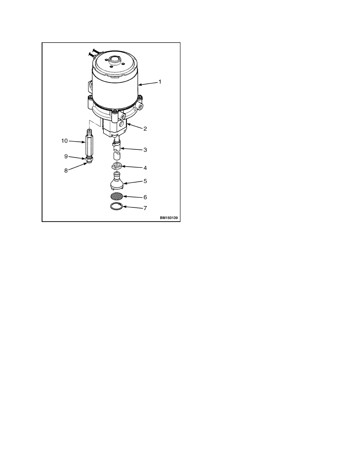
1. BRAKE ASSEMBLY
2. CAPSCREW
3. LOCKWAS
HER
4. WASHER
5. SNAP RING
6. WOODRUFF
KEY
7. BRAKE HUB
8. PRESSURE VALVE
9. LOCKING N
UT
10. VALVE BODY
Figure 14. Relief Valve Adjust
B80Z, B80Z
AC
, C80Z, C80Z
AC
, W65Z, and
W80Z
Refer to Relief Valve Pressure Check to determine if
adjustment is necessary.
1. Verify the key switch is in the OFF position and
the battery is disconnected.
2. Loosen and remove the three capscrews retain-
ing the lift pump and motor assembly to the
frame. Support the lift pump and motor assem-
bly as the screws are being removed and while
making adjustments. Tilt the lift pump and
motorassemblyawayfromtheframe.
3. Remove the cap on the relief valve.
4. Loosen the locking nut on the relief valve. See
Figure 14.
5. Adjust the relief valve screw in small increments.
Turn the adjustment screw clockwise to increase
pressure. Turn the adjustment screw counter-
clockwise to decrease pressure.
6. Tighten the lock nut and torque to 15 N•m
(11 lbf ft).
7. Connect the battery and turn the key switch to
the ON position.
8. Recheck the relief pressure. See Relief Valve
Pressure Check.
9. Repeat as necessary, until the correct relief pres-
sure is measured.
10. Install the cap on the relief valve.
11. Install the three capscrews securing the lift
pump and motor assembly to the frame. Torque
to 26 N•m (20 lbf ft).
12. Perform Step 13 through Step 23 in Relief Valve
Pressure Check to complete procedure.
25