1900 SRM 964 Lift Pump and Motor
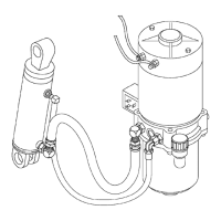
Legend for Figure 11
1. CAPSCREW
2. LIFT PUMP MOTOR
3. ADAPTER PLATE
4. COUPLING
5. TUBE
6. INLET TUBE
7. RETURN TUBE
8. STRAINER
9. CLAMP
10. STRAINER HOUSIN
G
11. SCREEN
12. RETAINER
13. TWO PIECE CLAMP
14. CAPSCREW
15. WASHER
16. RESERVOIR
17. FILLER ELBOW
18. FLAT SEAL
19. BREATHER/FILLER CAP
20. O-RING
21. O-RING
22. LOWERING ORIFICE
23. CAPSCREW
24. WASHER
25. LOWERING VALVE COIL
26. LOWERING VALVE C
ARTRIDGE
27. O-RING
28. CHECK VALVE
29. CHECK VALVE BALL
30. LIFT PUMP
31. RELIEF VALVE
ASSEMBLE
Assemble Pump
B60Z, B60Z
AC
,C6
0Z, C60Z
AC
,andW60Z
1. Clean and lubric
ate all components using clean
hydraulic oil.
2. Install the lowe
ring valve. See Lowering Valve,
Install.
3. Install the inle
t tube and strainer.
4. Install the new c
lamp.
5. Install the reli
ef valve. See Relief Valve, Install.
B80Z, B80Z
AC
,C
80Z, C80Z
AC
, W65Z, and W80Z
1. Clean and lubri
cate all components using clean
hydraulic oil.
2. Install the rel
ief valve. See Relief Valve, Install.
3. Install the che
ck valve. See Valve Repair, Install.
4. Install the low
ering valve. See Lowering Valve,
Install.
5. Install tubes a
nd related items to bottom of pump
as removed.
Install Pump Moto
r
WARNING
Always wear the proper protective equipment
including eye protection and petroleum-resis-
tant gloves when handling hydraulic oil. Thor-
oughly wash oil from exposed areas of skin as
soon as possible.
CAUTION
Protect the hydraulic system from dirt and
contaminants when servicing the hydraulic
system.
1. Lubricate the motor output shaft and the pump
input shaft with a light coating of Molycote
®
G-N
paste.
2. Install the coupling on the pump shaft.
3. Align the slot in the motor shaft with the cou-
pling. Lower the motor onto the pump, rotating
the body as necessary to engage the coupling.
4. Use the following procedure that applies to your
lift truck:
a. Align the pump assembly mounting holes
with the holes in the pump motor. Install the
capscrews and tighten to 8 N•m (71 lbf in).
b. Align the pump motor mounting holes with
the holes in the adapter plate. Install the
capscrews and tighten to 8 N•m (71 lbf in).
15