1900 SRM 964 Description of Operation
General
This section covers the troubleshooting and repair
procedures for the hydraulic components on B60Z,
B80Z,B60Z,B80Z
AC
, C60Z, C80Z, C60Z, C80Z
AC
,
W60Z, W65Z, and W80Z lift trucks.
It also includes the remove and install procedures for
the solenoid coil used to activate the lowering valve.
For troubleshooting and repairs of the electrical com-
ponents, see the sections Electrical System 2200
SRM 929, Electrical System 2200 SRM 1052, Elec-
trical System 2200 SRM 1357, or Electrical Sys-
tem 2200 SRM 1287. See the sections Curtis 1297
Transistor Motor Controller 2200 SRM 928, AC
Motor Controller 2200 SRM 1352, or AC Motor
Controller 2200 SRM 1286 for Controller functions.
Description of Operation
The hydraulic system of the B60Z, B80Z, B60Z,
B80Z
AC
, C60Z, C80Z, C60Z, C80Z
AC
, W60Z, W65Z,
and W80Z lift trucks includes:
• Reservoir
• Pump
• Check Valve
• Relief Valve
• Lowering Valve
• Lift Cylinder
• Connecting Hoses and Tubes
WARNING
Always wear the proper protective equipment
including eye protection and petroleum-resis-
tant gloves when handling hydraulic oil. Thor-
oughly wash oil from exposed areas of skin as
soon as possible.
Never check for leaks by putting hands on
hydraulic lines or components under pressure.
Hydraulic oil under pressure can be injected
into the skin.
Completely lower forks to relieve hydraulic
pressure before disassembling any part of
the lift pump or disconnecting any hydraulic
hoses.
The hydraulic oil is hot at normal operating
temperatures. Be careful when draining the
oil.
CAUTION
Protect the hydraulic system from dirt and
contaminants when servicing the hydraulic
system.
Never operate the pump without the proper
amount of oil in the hydraulic system. The
operation of the hydraulic pump with low oil
levels will damage the pump.
The reservoir contains the hydraulic fluid necessary
for the operation of the system. It acts as a heat sink
to provide cooling. As the hydraulic oil leaves the
reservoir, it passes through a strainer in the reser-
voir. See Figure 1.
The hydraulic pump provides the flow of the hy-
draulic oil which activates the cylinder.
A check valve allows flow of the hydraulic oil in one
direction only. In this hydraulic system, it prevents
the oil from flowing backwards through the pump.
A relief valve limits maximum system pressure to
protect the hydraulic system components.
The lowering valve is a normally closed valve. When
it opens, hydraulic oil from the lift cylinder is allowed
to return to the reservoir, and the forks lower.
The lift cylinder rod extends to operate the lift link-
ages to raise the forks.
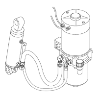
The connecting hoses and tubing connect the various
hydraulic components in the lift truck to complete
the hydraulic circuit. See Figure 2 and Figure 3.
1