Description of Operation 1900 SRM 964
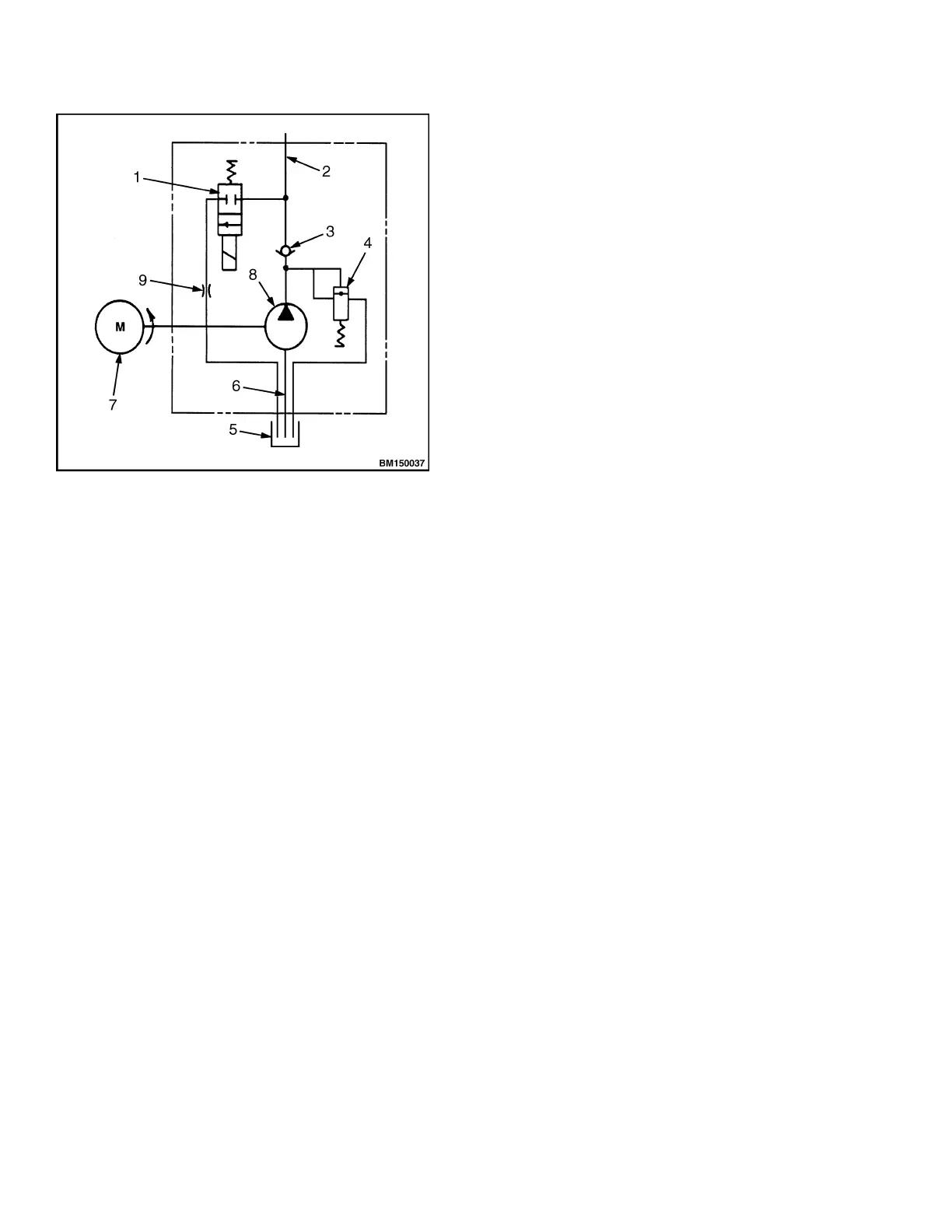
1. LOWERING SOLENOID VALVE
2. TO LIFT CYLINDER
3. CHECK VALVE
4. RELIEF VALVE
5. RESERVOIR
6. INLET LINE
7. PUMP MOTOR
8. LIFT PUMP
9. ORIFICE
Figure 1. Lift Pump and Motor Assembly
Schematic
LIFTING A LOAD
To raise a load, the lift button must be depressed. De-
pressing this switch will activate the lift pump mo-
tor. Torque is transferred to the pump from the mo-
tor through the motor shaft and the coupling.
Hydraulic oil is pumped through the system as
the pump begins to operate. Atmospheric pressure
forces oil into the low pressure area at the pump
inlet. Air, which is drawn into the reservoir through
the breather, displaces the pumped oil, allowing oil
to be sent through the system. See Figure 1.
As oil is pushed out of the pump, it passes through a
one-way check valve to the lift cylinder. The check
valve prevents oil from flowing back to the pump
when lifting ceases, holding the lift cylinder in the
raised position until lowered.
The piston will begin to lift the load when fluid pres-
sure acting against it is high enough to overcome the
weight of the load.
When the piston is fully extended to the end of its
stroke or if the load is too heavy, pressure will con-
tinue to build until the rated pressure needed to op-
erate the relief valve is reached. When this occurs,
the relief valve, which is normally closed, is forced
back against its spring, creating a path for the fluid
to flow back to the reservoir.
Once relief pressure is reached, hydraulic oil will con-
tinue to be diverted from the relief valve to the reser-
voir until the lift button is released, controller time-
out is reached, or electrical power is interrupted.
LOWERING A LOAD
A load is lowered by depressing the lower button.
When the lower button is depressed, electric current
is sent to the normally closed solenoid lowering valve,
which causes it to change position and open a path
for the trapped hydraulic oil to flow from the cylin-
der back to the reservoir.
HYDRAULIC LINES
1. All hydraulic hoses and tubes must be thor-
oughly cleaned before installation.
2. When making repairs, use the least number of
fittings and connections to minimize flow resis-
tance and the possibility of leakage.
HYDRAULIC OIL
The hydraulic oil in the system performs the dual
function of the power transmission and lubrication.
Using the correct fluid is essential to proper system
operation. See the section Periodic Maintenance
8000 SRM 919, Periodic Maintenance 8000 SRM
1032, Periodic Maintenance 8000 SRM 1368, or
Periodic Maintenance 8000 SRM 1298 for the rec-
ommended hydraulic oil.
The hydraulic oil level should be checked first when
troubleshooting lifting problems. Low oil levels may
make it appear that a problem exists with the battery
or hydraulic system.
2