1900 SRM 964 Special Precautions
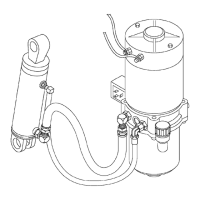
Legend for Figure 3
1. SOCKET-HEAD S
CREW
2. LOCKWASHER
3. MOUNTING BRACKET
4. LOCKWASHER
5. CAPSCREW
6. LOCKWASHER
7. CAPSCREW
8. LIFT PUMP AND MOTOR ASSEMBLY
9. ADAPTER
10. FITTING
11. TUBE ASSEMBLY
12. ADAPTER
13. ELBOW FITTING
14. HOSE ASSEMBLY
15. ELBOW FITTING
16. LIFT CYLINDER ASSEMBLY
CLEAN
Adhere to the following precautionary steps to en-
sure that the hydraulic system remains clean.
1. Clean the reservoir and pump area to prevent
contaminants from entering the hydraulic sys-
tem.
2. Clean (flush) the entire system when a failure is
encountered to make sure all paint, metal chips,
welding shot, and debris are removed.
3. Filter each change of oil to prevent the introduc-
tion of contaminants into the system.
4. Provide continuous protection from airborne con-
tamination by keeping the breather cap clean
and serviceable.
SOUND LEVEL
Hydraulic system noise may be caused by both im-
properly selected oil and loose or damaged system
components.
• Cavitation - Can be caused by high fluid viscos-
ity, cold fluid temperatures, or a restriction in the
inlet screen or inlet tubing. At startup, low temper-
atures can cause pump noises due to cavitation.
• Aerated Hydraulic Oil - Results in system noise
that is similar to cavitation. Aerated oil is caused
by the ingestion of air through the joints of the in-
let lines and high-velocity discharge lines. Aera-
tion can also be caused by oil discharging above the
fluid level in the hydraulic reservoir. Aerated hy-
draulic oil occurs when air does not have sufficient
time to escape from the fluid while in the reservoir
before recycling through the system.
Special Precautions
WARNING
The capaci
tor in the transistor controller can
hold an ele
ctrical charge after the battery is
disconnec
ted. To prevent an electrical shock
and person
al injury, discharge the capacitor
before ins
pecting or repairing any component
in the dri
ve unit compartment. Wear safety
glasses.
Make certain that the battery has
been disc
onnected.
CAUTION
To avoid controller damage, always disconnect
the battery, discharge the capacitor, and never
put power to the controller while any power
wires are disconnected. Never short any con-
troller terminal or motor terminal to the bat-
tery. Make sure to use proper procedure when
servicing the controller.
1. Verify that the key switch is in the OFF position
and the battery connector is completely discon-
nected.
2. Discharge the capacitors in the controllers by
connecting a 200-ohm, 2-watt resistor across
the controller’s B+ and B
terminals. DO NOT
short across the motor controller terminals
withascrewdriverorjumperwire. Removethe
200-ohm, 2-watt resistor before reconnecting the
battery. See Figure 4 or Figure 5.
5