Chapter 10 Appendix
POWER CON
PCON-CB/LC
247
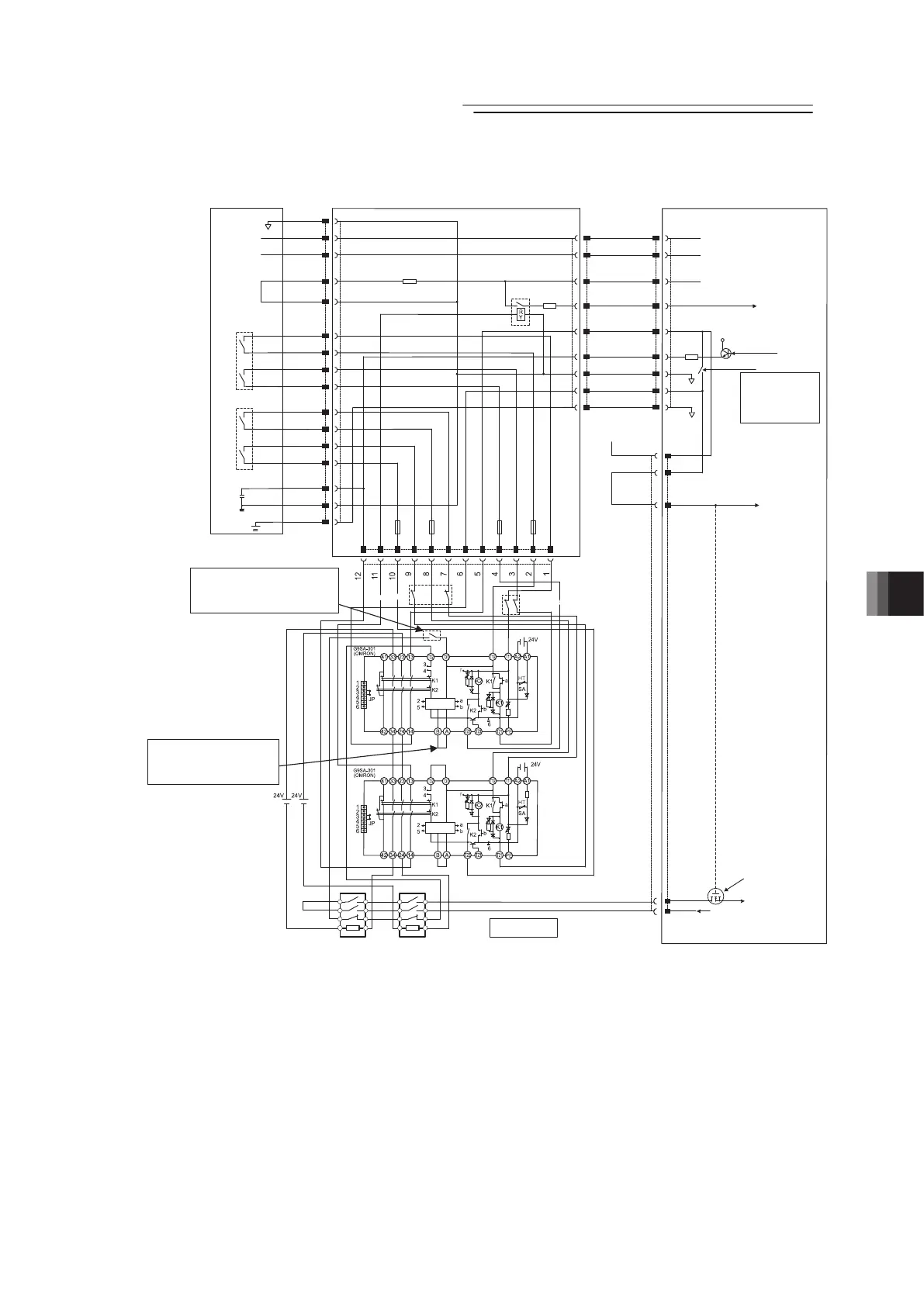
● Detailed category 3 or 4 circuit example
SG
SGA
SGB
RTS
CTS
EMG1-
EMG1+
EMG2-
EMG2+
EMB1-
EMB1+
EMB2-
EMB2+
DC24V+
DC24V-
EMBOUT
EMBIN
EMB2+
EMB2-
EMB1+
EMB1-
EMGOUT
EMGIN
EMG2+
EMG2-
EMG1+
EMG1-
1
2
3
4
5
6
7
8
9
MPI
MPO
*EMGSTR
ENB
VP24
PCON
TP Connection Detecting
TP Detection
T24V…Output
Bypass relay…OPEN
TP Not Detected
T24V…Not Output
Bypass relay…CLOSE
TP
Emergency Stop SW
Enable SW
Shell
1
2
3
13
14
9
12
6
5
23
24
25
22
7
26
Motor Power
Cutoff Relay
RCB-LB-TGS
SGA
SGB
EMGA
24V
EMGB
1
2
3
4
5
6
7
8
9
5V
+
Reset SWReset SW
Emergency Stop SW
Emergency Stop SW
Reset SW
Control
Circuit
Control
Circuit
Solenoid Contactor Solenoid Contactor
External Emergency
Stop Circuit category 4
For Category 4, insert Reset
Switch as shown in the diagram.
For Category 3, layout the wiring
without inserting Reset Switch.
For Category 4, make the
connection of A and B open.
For category 3, make a short
circuit between A and B.
24V
Motor Power Supply
S1
S2
EMG-
24V
Controller
 Loading...


