Appendix A. RJ-45 pin specifications
When you connect the switch to another switch, a bridge, or a hub, a normal cable
is necessary. Review the documentation that comes with these products for
matching cable pin assignments.
The following illustration and table show the standard RJ-45 receptacle/connector
and their corresponding pin assignments for the switch-to-network adapter
connection, and the normal cable for the switch-to-switch/hub/bridge connection.
Table 6. Standard Category 3 cable, RJ-45 pin assignment
RJ-45 Connector pin assignment
Contact (pin number) Media direct interface signal
1 Tx + (transmit)
2 Tx - (transmit)
3 Rx + (receive)
4 Not used
5 Not used
6 Rx - (receive)
7 Not used
8 Not used
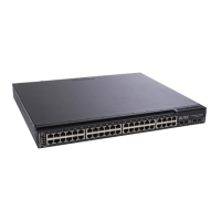
The four external Ethernet ports of this switch module are auto-configuring and do
not require straight-through or crossover cables.
© Copyright IBM Corp. 2002 115
 Loading...


