Installing the light path diagnostics panel
Use this information to install the light path diagnostics panel.
Before you begin
Before you install the light path diagnostics panel, complete the following steps:
1. Read “Safety” on page v and “Installation guidelines” on page 487.
2. If the compute node is installed in an IBM Flex System chassis, remove it (see
“Removing a compute node from a chassis” on page 489 for instructions).
3. Carefully lay the compute node on a flat, static-protective surface, orienting the
compute node with the bezel pointing toward you.
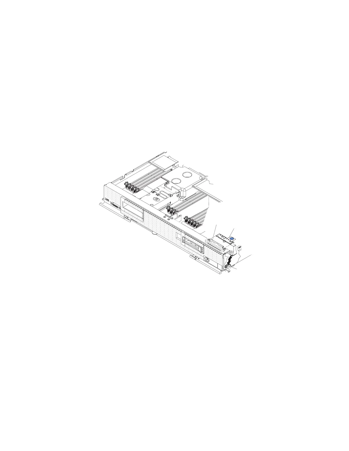
Procedure
To install a light path diagnostics panel, complete the following steps.
Bracket
Light path
diagnostics
panel
Connector
1. Remove the cover (see “Removing the compute node cover” on page 498).
2. Connect the cable on the system board.
3. Align the light path diagnostics panel with the bracket.
4. Press the light path diagnostics panel securely in the bracket.
What to do next
After you install the light path diagnostics panel, complete the following steps:
1. Install the cover onto the compute node (see “Installing the compute node
cover” on page 500 for instructions).
2. Install the compute node into the chassis (see “Installing a compute node in a
chassis” on page 490 for instructions).
Removing the USB flash drive
Use this information to remove the USB flash drive.
Chapter 7. Installing, removing, and replacing compute node components 527