1. Install the cover onto the compute node (see “Installing the compute node
cover” on page 500 for instructions).
2. Install the compute node into the chassis (see “Installing a compute node in a
chassis” on page 490 for instructions).
3. See the documentation that comes with the expansion adapter for device-driver
and configuration information to complete the installation.
Removing the light path diagnostics panel
Use this information to remove the light path diagnostics panel.
Before you begin
Before you remove the light path diagnostics panel, complete the following steps:
1. Read “Safety” on page v and “Installation guidelines” on page 487.
2. If the compute node is installed in an IBM Flex System chassis, remove it (see
“Removing a compute node from a chassis” on page 489 for instructions).
3. Carefully lay the compute node on a flat, static-protective surface, orienting the
compute node with the bezel pointing toward you.
Procedure
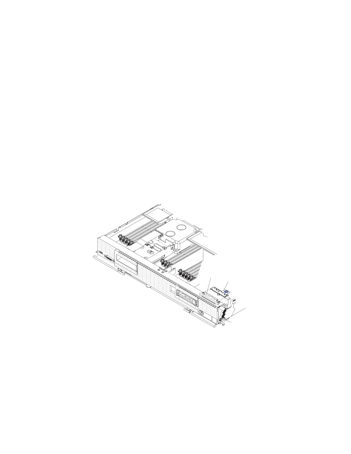
To remove the light path diagnostics panel, complete the following steps.
Bracket
Light path
diagnostics
panel
Connector
1. Remove the cover (see “Removing the compute node cover” on page 498).
2. Pull the light path diagnostics panel out of the bracket.
3. Disconnect the cable from the system board.
4. Lift the light path diagnostics panel from the compute node.
What to do next
If you are instructed to return the light path diagnostics panel, follow all
packaging instructions, and use any packaging materials for shipping that are
supplied to you.
526 IBM Flex System x440 Compute Node Types 7917 and 2584: Installation and Service Guide