Chapter 5. Rack planning 149
5.7.3 10 Gb Ethernet, one port per node
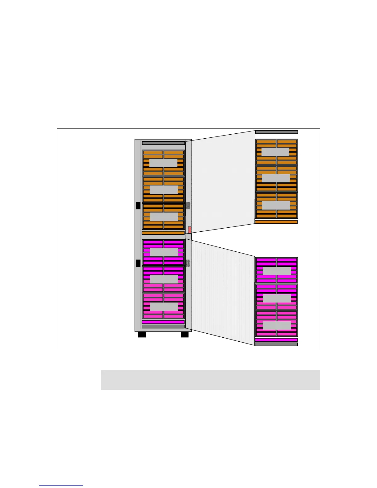
Figure 5-21 shows a network with one 10 Gb Ethernet connection per compute
node. On the left side is a rack with six chassis for a total of 72 CPU nodes. Two
48 port 10 Gb switches and two 48 port 1 Gbps Ethernet switches provide the
network connectivity.
Figure 5-21 10 Gb Ethernet, one port per node configuration
48 Port 10 Gb Ethernet Switch
48 Port 1GBe 36 Down 2 10G Up
48 Port 1GBe 36 Down 2 10G Up
48 Port 10 Gb Ethernet Switch
10 Gb Enet Switch 1
10 Gb Enet Switch 2
Cable Channel 1 Cable Channel 2
Cable Channel 3 Cable Channel 4
1
2
3
4
5
6
13
14
15
16
17
18
7
8
9
10
11
12
19
20
21
22
23
24
31
32
33
34
35
36
25
26
27
28
29
30
37
38
39
40
41
42
1G Ethernet Switch 1
1G Ethernet Switch 2
1
3
5
7
9
11
2
4
6
8
10
12
1
3
5
7
9
11
2
4
6
8
10
12
1
3
5
7
9
11
2
4
6
8
10
12
1
3
5
7
9
11
2
4
6
8
10
12
1
3
5
7
9
11
2
4
6
8
10
12
1
3
5
7
9
11
2
4
6
8
10
12
Chassis 1
Chassis 2
Chassis 3
Chassis 4
Chassis 5
Chassis 6
48 Port 1GBe 36 Down 2 10G Up
48 Port 10 Gb Ethernet Switch
Chassis 1
Chassis 2
Chassis 3
48 Port 10 Gb Ethernet Switch
48 Port 1GBe 36 Down 2 10G Up
Chassis 4
Chassis 5
Chassis 6
Building Block 1
Building Block 2
Filler panel: 1U filler (part number 00Y3011) is placed in rack units 21 and 41
to prevent hot air recirculation.