Chapter 5. Rack planning 151
In Figure 5-22 on page 150, each node has two colors. This indicates that each
node is connected to two different switches to provide redundancy.
5.7.5 Management network
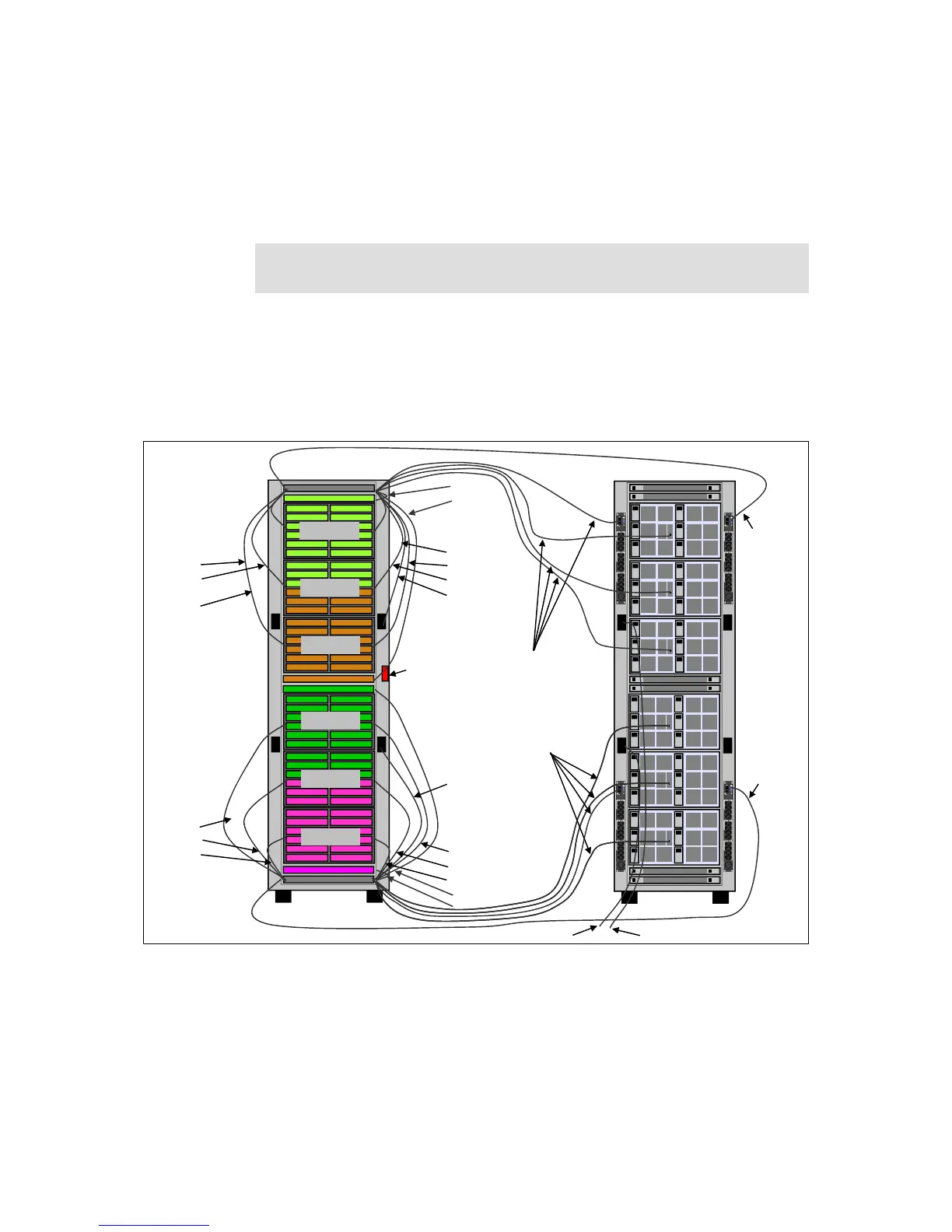
Figure 5-23 shows the 1 Gb Ethernet management network for a solution with
four monitored PDUs. The 1 Gb management switches are shown in rack units 1
and 42.
Figure 5-23 Management network
Filler panel: A 1U filler (part number 00Y3011) is placed in rack unit 22 to
prevent hot air recirculation.
36 Port IB 18 Down 18 UP
36 Port IB 18 Down 18 UP
48 Port 1GBe 36 Down 2 10G Up
48 Port 1GBe 36 Down 2 10G Up
36 Port IB 18 Down 18 UP
36 Port IB 18 Down 18 UP
IB Switch 1
IB Switch 2
IB Switch 3
IB Switch 4
Cable Channel 1 Cable Channel 2
Cable Channel 3 Cable Channel 4
1
2
3
4
5
6
13
14
15
16
17
18
7
8
9
10
11
12
19
20
21
22
23
24
31
32
33
34
35
36
25
26
27
28
29
30
37
38
39
40
41
42
1G Ethernet Switch 1
1G Ethernet Switch 2
1
3
5
7
9
11
2
4
6
8
10
12
1
3
5
7
9
11
2
4
6
8
10
12
1
3
5
7
9
11
2
4
6
8
10
12
1
3
5
7
9
11
2
4
6
8
10
12
1
3
5
7
9
11
2
4
6
8
10
12
1
3
5
7
9
11
2
4
6
8
10
12
Chassis 1
Chassis 2
Chassis 3
Chassis 4
Chassis 5
Chassis 6
(6X) Cat5
(6X) Cat5
(6X) Cat5
(6X) Cat5
(6X) Cat5
(6X) Cat 5
(1X) Cat5
(1X) Cat5
(1X) Cat5
(1X) Cat5
(1X) Cat5
(2X) SFP+ Uplink (2X) SFP+ Uplink
Door Latch
(6X) Cat5
(6X) Cat5
(6X) Cat5
(2X) SFP+ Uplink
(2X) SFP+ Uplink
(6X) Cat5
(6X) Cat5
(6X) Cat5
(1X) Cat5
(1X) Cat5
(1X) Cat5
(1X) Cat5