Chapter 3. IBM NeXtScale n1200 Enclosure 43
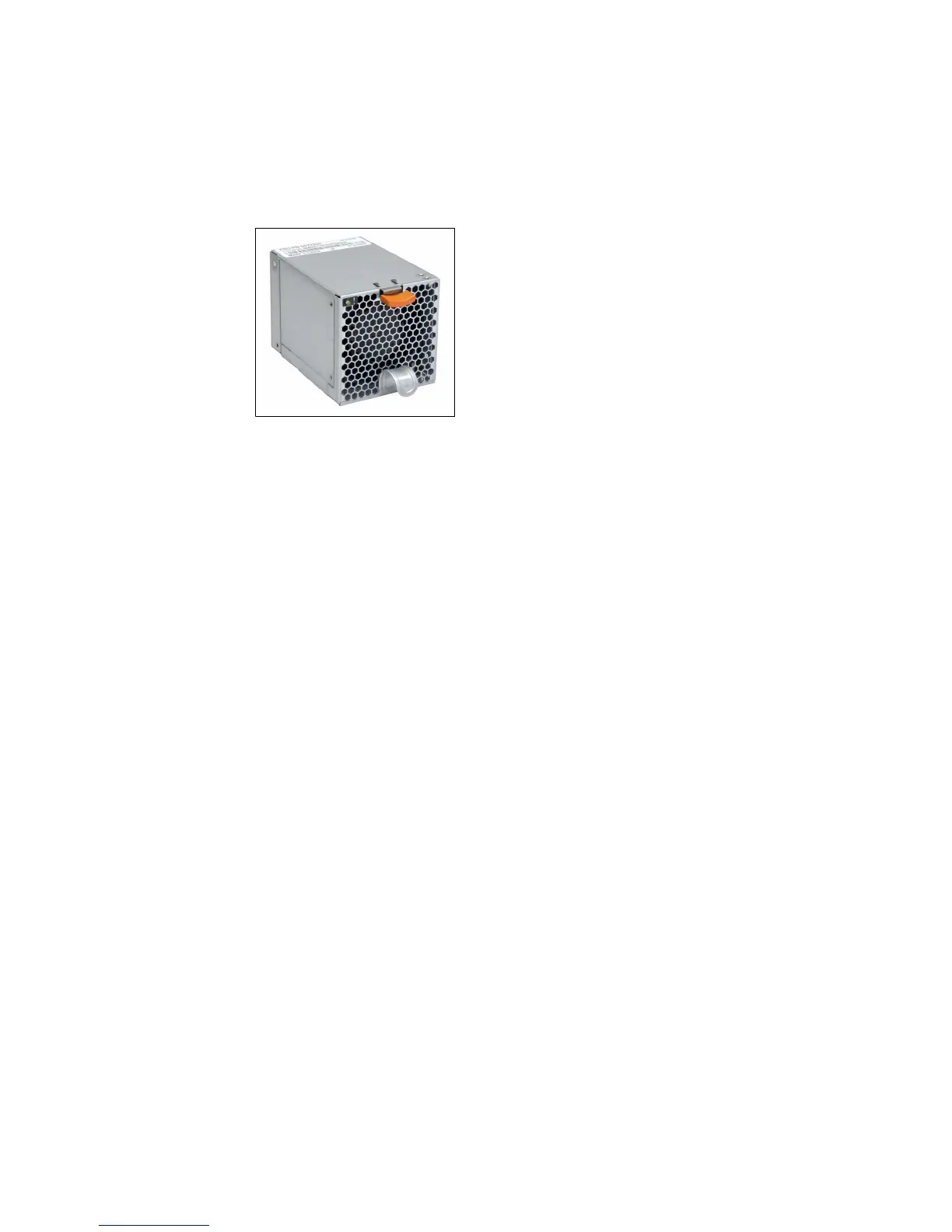
The 80 mm fan module is shown in Figure 3-8.
Figure 3-8 80 mm fan module
Fan module controls and indicators
Each fan module has a Fault LED. When this LED is lit (yellow), it indicates that
the fan module failed.
The fan modules are not dedicated to cool a specific node. If there is a fan
module failure, the remaining functional fans speed up (if required) under the
control of the FPC to provide sufficient cooling to the chassis elements.
There are two logical cooling zones in the enclosure, as shown in Figure 3-9 on
page 44. Five fan modules on each side correspond to the six compute nodes on
that same side of the chassis.