System-board layouts
Illustrations show the connectors and LEDs on the system board. The illustrations might differ slightly
from your hardware.
System-board connectors
Blade server components attach to the connectors on the system board.
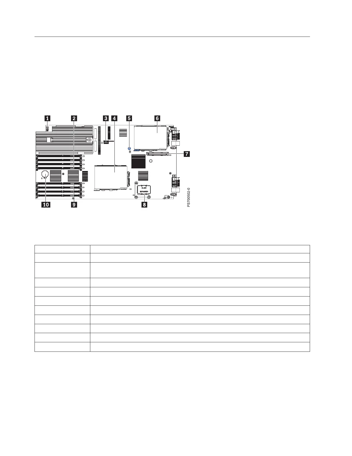
Figure 3 shows the connectors on the base unit system board in the blade server.
Table 2 shows connector descriptions.
Table 2. PS700 connectors
Callout PS700 blade server connectors
1 Operator panel connector
2 DIMM 1-4 connectors (See Figure 4 on page 9 for individual connectors.) Expansion unit
(SMP) connector
3 Management card connector (P1-C9)
4 SAS hard disk drive connector (P1-D2)
5 Light Path Blue Button
6 SAS hard disk drive (P1-C10)
7 CIOv (1Xe) expansion card connector (P1-C11)
8 High-Speed (CFFh) expansion card connector (P1-C12)
9 DIMM 5-8 connectors (See Figure 4 on page 9 for individual connectors.)
10 3V lithium battery connector (P1-E1)
Figure 4 on page 9 shows individual DIMM connectors.
Figure 3. PS700 system-board connectors
8 Power Systems: Problem Determination and Service Guide for the IBM Power PS700 (8406-70Y)
 Loading...


