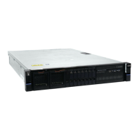
Figure 123. Fan module LED
Procedure
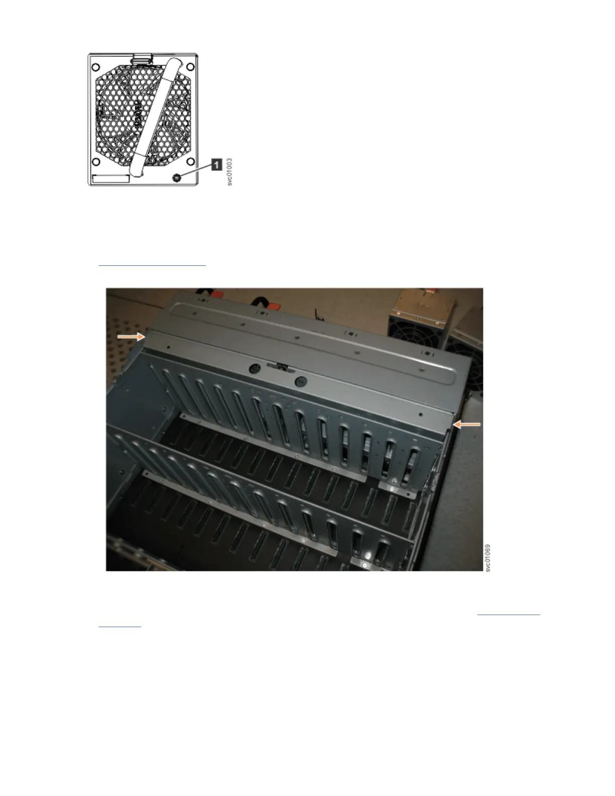
1. Using a cross head screwdriver, remove the narrow metal cover that is over the FIBs, as shown in
Figure 124 on page 113. The screws are on each side of the chassis. Place the cover and cover screws
in a safe location.
Figure 124. Location of the FIB cover
2. Use a cross head screwdriver to loosen the retaining screws on the FIB, as shown in Figure 125 on
page 114.
Chapter 4. Installing an optional 5U SAS expansion enclosure
113
 Loading...


