Up to three electrical Ethernet cables can be connected to the SAN Volume Controller 2145-SV1 . The
cable connection table indicates the number of cables to connect. Connect to the ports in numerical
order, beginning with Ethernet port 1.
Procedure
To connect the SAN Volume Controller 2145-SV1 to the SAN and to the Ethernet network, complete the
following steps.
1. Connect the Ethernet cables to the Ethernet ports on the rear of the SAN Volume Controller 2145-
SV1 .
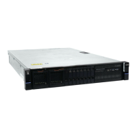
Ports 1-3 are standard. If you have 10 Gbps or 25 Gbps Optical Ethernet adapters that you want to
connect to an Ethernet switch for iSCSI communications, 11 Ethernet ports might be available. Figure
31 on page 27 shows one of the possible node congurations.
Figure 31. Ethernet ports on the rear of the SAN Volume Controller 2145-SV1
1 - 3 10 Gbps Ethernet ports 1-3
4 - 7 10 Gbps optical Ethernet ports 4-7
2. Connect the other end of the Ethernet cable to the proper connector on the Ethernet hub or switch.
3. Optional: If the Fibre Channel feature is installed, you can connect Fibre Channel cables to the Fibre
Channel ports as required by your conguration.
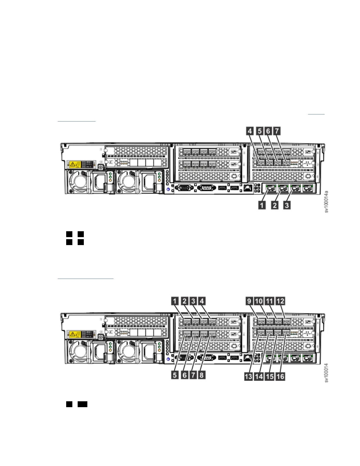
Figure 32 on page 27 shows an example of the device with 16 Gbps Fibre Channel adapters that are
installed in slots 3, 4, and 6. A 10 Gbps Optical Ethernet adapter is used for Fibre Channel over
Ethernet (FCoE) communications and is installed in slot 7, providing additional Fibre Channel ports.
Figure 32. Fibre Channel ports
1 - 16 Fibre Channel ports 1-16
Note: If you are installing a hot-spare node, the Fibre Channel cabling must be identical for all nodes
of the system. In other words, port 1 on every node must be connected to the same fabric, port 2 on
every node must be connected to the same fabric, and so on.
Chapter 2. Installing the SAN Volume Controller 2145-SV1 hardware
27
 Loading...


