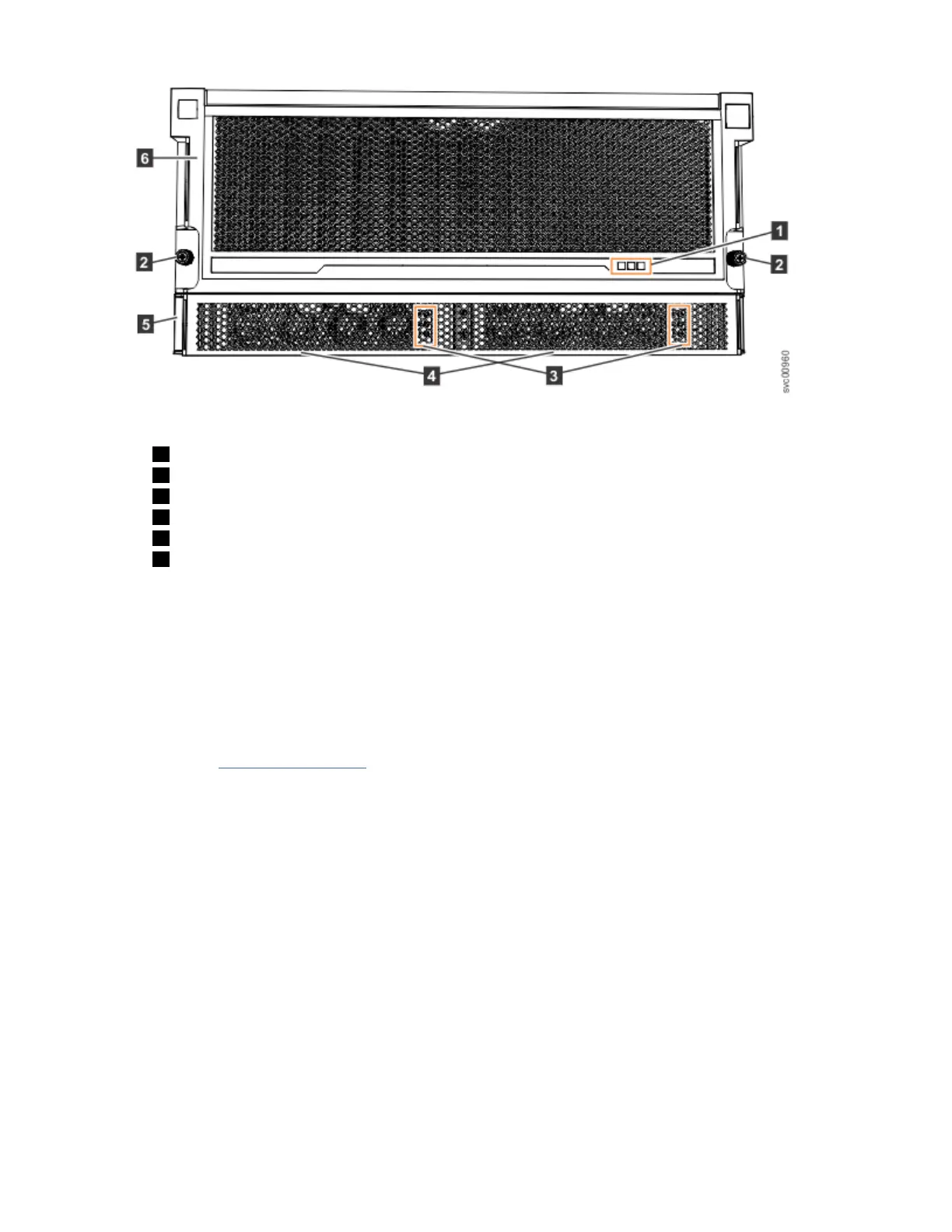
Figure 76. Features on the front of the 2077-92F, 2077-A9F expansion enclosure
1 Display panel LEDs
2 Rack retention thumb screws
3 Power supply unit LEDs
4 Power supply units (PSUs)
5 PSU fascia (1U)
6 Front fascia (4U)
Each PSU has a power supply connector and power cable, which are accessible from the back of the
enclosure. Power is provided by plugging a C19-C20 power cable into each power supply unit and, if
necessary, turning on the power source. The expansion enclosure does not have a power button.
Procedure
1. Connect the C19-C20 power cables to the power connectors on the rear of the expansion enclosure.
The enclosure automatically powers on and begins its Power On Self-Tests (POST).
2. Secure the power cables in the cable retainer at each power connector on the rear of the enclosure, as
shown in Figure 77 on page 78. Also, ensure that each cable is installed along one of the cable
management arms. The cable management arms also support the SAS cables.
Chapter 2. Installing the system hardware
77
 Loading...