To replace the chassis fan, reverse the previous steps.
Notes:
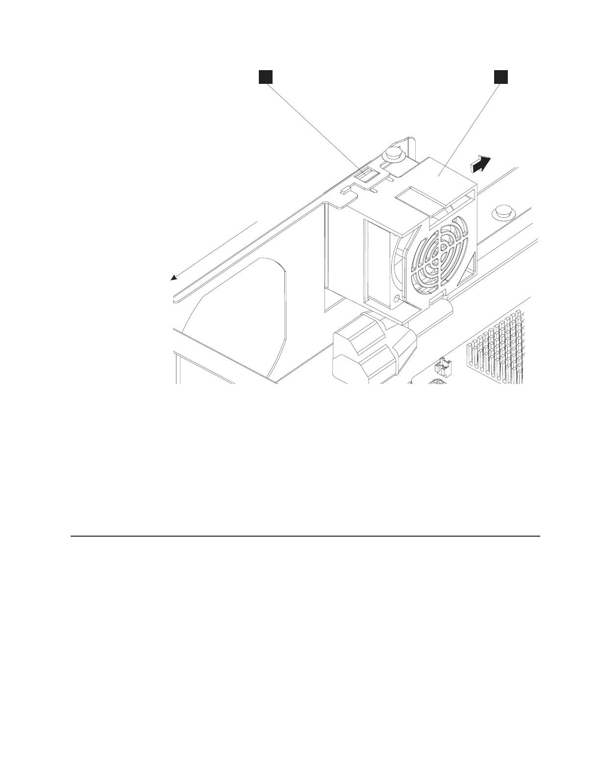
1. When doing the reverse of Step 3 on page 42, be sure that the two bottom lock
tabs on the fan duct engage their slots on the pullout tray sidewall.
2. Be sure to route the chassis fan connector cable under the main riser card
frame and main riser card. Do not route it over the frame, or it will interfere with
pullout tray movement in the unit frame.
3. Reconnect the fan.
Replacing the processor fan (Models 723 and E23 only)
To remove the processor fan:
1. Follow the steps in “Removing the pullout tray” on page 37 to remove the
pullout tray completely from the unit frame.
2. Follow the steps in “Replacing an I/O module” on page 40 to remove the I/O
modules from the system.
3. Carefully disconnect the fan connector cable from the plug on the system board
that is next to the processor.
4. Remove the four screws holding down the fan to remove the fan.
To replace the processor fan, reverse the previous steps.
A B
Front of Machine
Figure 30. Removing the chassis fan with duct
Chapter 2. Removal and replacement procedures 43
 Loading...