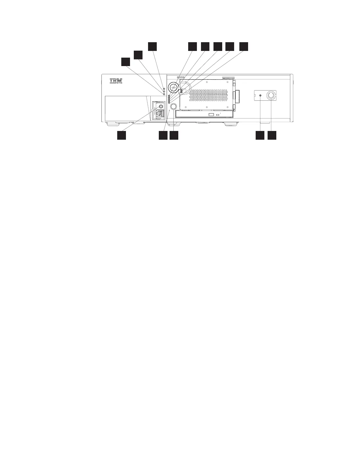
A Power LED
B LED 1, processor fan failure
C LED 2, system board failure
D LED 3, upper HDD failure
E LED 4, lower HDD failure
F LED 5, power supply failure
G Uninterruptible power supply switch (only with wide footprint and
uninterruptible power supply installed; otherwise covered)
H Uninterruptible power supply indicator (only with wide footprint and
uninterruptible power supply installed; otherwise covered)
I System power switch
J Recessed dump switch
K Headphone jack (Models 743, C43, E43, 783, E83, 784, C84, and E84
only)
L Information LED
M Hard disk or optical drive activity LED
Note: G and H are available only if you install the optional uninterruptible power
supply.
Connectors
The SurePOS 700 Series offers a unique configuration for connecting POS I/O
devices. Most of the POS-specific I/O function is contained on a riser card that
connects into the system board.
The SurePOS models support RS-485 POS I/O (4694 family), powered USB I/O
(IBM SurePOS 700 family), and powered RS-232 I/O. A unique tailgate design,
which includes IBM SurePort adapters, provides different configurations of I/O that
you can later upgrade or change in the field. The rear I/O panels are attached to
the riser card.
Table 5 on page 12 provides a summary of the available I/O ports.
B
L
M
K J I H G
A C D E
F
Figure 5. Front panel controls and indicators.
Note: Use of the front headphone jack overrides the rear line-out jack
Chapter 1. Introducing the SurePOS 700 models 11
 Loading...