To replace the DASD cage, reverse the previous steps.
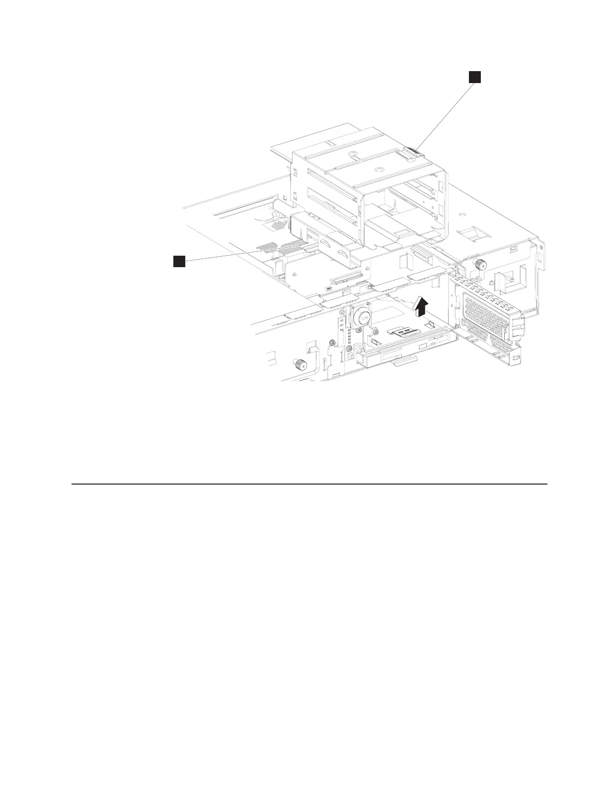
Note: Ensure that the guide tab (C) aligns with its slot on the pullout tray base
(not shown), which will help to guide the DASD riser card into the DASD slot
on the system board.
Replacing the power supply
To remove the power supply:
1. Follow the steps in “Replacing the spline” on page 46 to remove the spline.
2. Note the cable routing, and then carefully disconnect the internal power
connector from the system board.
Note: The system-board main power connector has a latch on the right side of
it that you must push to disconnect it.
3. Disconnect the power cable from the riser card.
Note: The riser card main power connector has a latch on the bottom of it that
you must push to disconnect it.
4. Disconnect the internal power cable rear coupling from the power supply.
5. Completely loosen the spring screw holding the front of the power supply to the
front of the pullout tray.
6. Lift to remove the power supply from the unit.
To replace the power supply, reverse the previous steps.
B
C
Figure 37. Removing the DASD cage
Chapter 2. Removal and replacement procedures 51
 Loading...