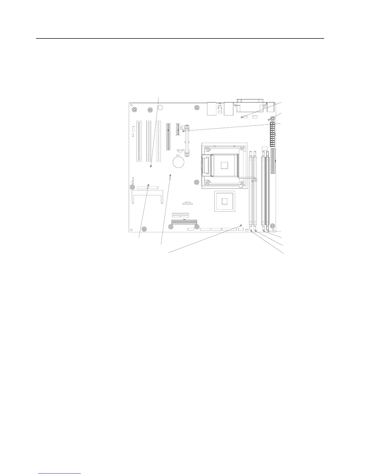
System-board LEDs
The following illustration shows the LEDs on the system board. You might have to
refer to this illustration when you are solving problems with the server.
Note: The server does not contain a light path diagnostics panel.
Standby power LED
System fan error LED
Microprocessor
fan error LED
mini-BMC heartbeat LED
VRD power fault LED
System power LED
DASD fan error LED
DIMM 1 error LED
DIMM 2 error LED
DIMM 3 error LED
DIMM 4 error LED
Use the system-board LEDs to diagnose system errors. An error LED is lit to
indicate a problem with a specific component. After a problem is corrected, its LED
will not be lit the next time that the server is restarted; if the problem remains, the
LED will be lit again. For additional information, see the Problem Determination and
Service Guide on the IBM System x Documentation CD.
72 System x3200 Type 4362 and 4363: Installation Guide

 Loading...


