Table 8. Memory rank sparing mode DIMM population sequence (continued)
Number of DIMMs
Number of installed
microprocessor DIMM connector
Eighth pair of DIMMs 2 16, 17
Ninth pair of DIMMs 2 20, 21
Tenth pair of DIMMs 2 23, 24
Eleventh pair of DIMMs 2 19, 22
Twelfth pair of DIMMs 2 15, 18
Note: DIMM connectors 3, 6, 7, 10, 15, 18, 19, and 22 are not used in memory rank
sparing mode when UDIMMs are installed in the server.
Installing a DIMM
To install a DIMM, complete the following steps:
1. Read the safety information that begins on page vii and “Installation guidelines”
on page 37.
2. Turn off the server and peripheral devices and disconnect the power cords and
all external cables, if necessary.
3. Unlock and remove the left-side cover (see “Removing the left-side cover” on
page 60).
4. Remove the air baffle if installed (see “Removing the air baffle” on page 60).
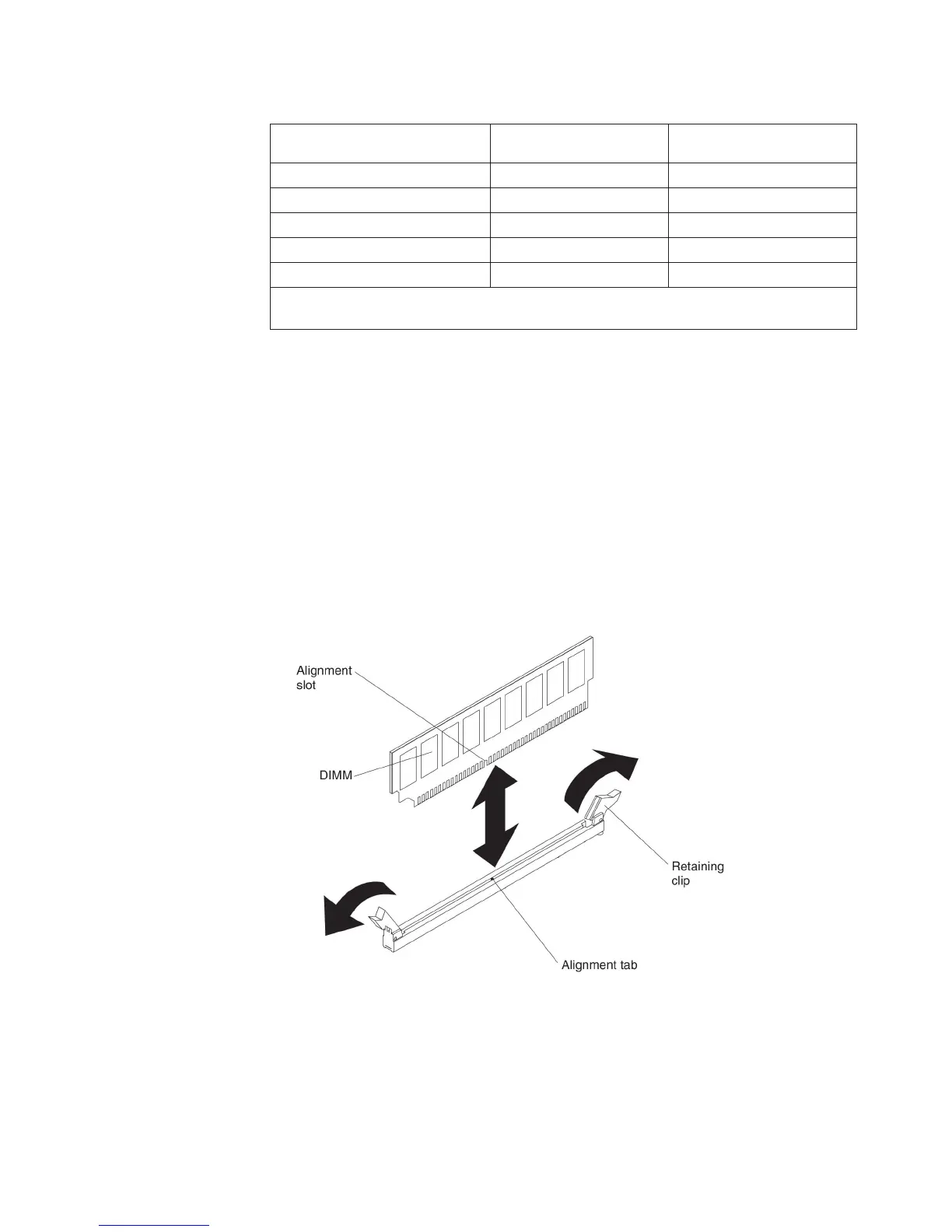
5. Open the retaining clip on each end of the DIMM connector.
Attention: To avoid breaking the retaining clips or damaging the DIMM
connectors, open and close the clips gently.
6. Touch the static-protective package that contains the DIMM to any unpainted
metal surface on the outside of the server. Then, remove the DIMM from the
package.
7. Turn the DIMM so that the alignment slot align correctly with the alignment tab.
8. Insert the DIMM into the connector by aligning the edges of the DIMM with the
slots at the ends of the DIMM connector (see “System-board internal
connectors” on page 31for the locations of the DIMM connectors).
Chapter 2. Installing optional devices 83