Table 2. Light path diagnostics panel LEDs (continued)
v Follow the suggested actions in the order in which they are listed in the Action column until the problem
is solved.
v If an action step is preceded by "(Trained technician only)," that step must be performed only by a trained
technician.
LED Description Action
HDD A hard disk drive has failed or is
missing.
1. If the CONFIG LED is not lit, complete the following steps
to correct the problem:
a. Check the LEDs on the hard disk drives for the drive
with a lit status LED and reseat the hard disk drive.
b. Reseat the hard disk drive backplane.
c. For more information, see the “Hard disk drive
problems” under the Troubleshooting tables in the
Problem Determination and Service Guide.
d. If the error remains, replace the following components
one at a time, in the order listed, restarting the server
after each:
1) Replace the hard disk drive.
2) Replace the hard disk drive backplane.
e. If the problem remains, go to http://www.ibm.com/
systems/support/supportsite.wss/
docdisplay?brandind=5000008&lndocid=SERV-CALL.
2. If the HDD LED and the CONFIG LED are lit, complete
the following steps to correct the problem:
a. Check the microprocessor installed is Intel E5-2690. If
it is, check the 2.5-inch hard disk drives installed is
lesser than eight.
b. Check the system-error logs for information about the
error. Replace any component that is identified in the
error log.
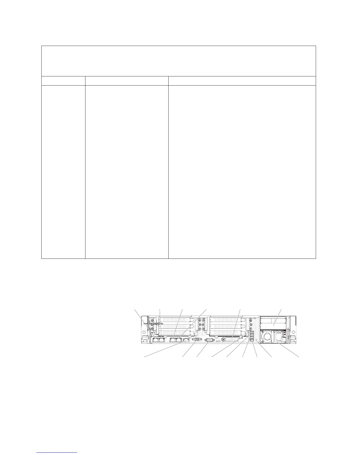
Rear view
The following illustration shows the connectors on the rear of the server.
Video Serial
Power supply 1
Power supply 2
Ethernet1
(shared system
management ethernet)
Ethernet2 Ethernet3 Ethernet4
System-management
(ethernet)(dedicated)
10G ethernet
(with optional
10G ethernet card)
USB5USB3 USB4 USB6 NMI
button
Ethernet connectors: Use either of these connectors to connect the server to a
network. When you enable shared Ethernet for IMM2 in the Setup utility, you can
access the IMM2 using either the Ethernet 1 or the system-management Ethernet
(default) connector. See “Using the Setup utility” on page 145 for more information.
Power-cord connector: Connect the power cord to this connector.
Chapter 1. The System x3650 M4 server 23

 Loading...


