Table 6. System-pulse LEDs (continued)
LED Description Action
IMM2 heartbeat IMM2 heartbeat boot process. The following steps describe the
different stages of the IMM2 heartbeat
sequencing process.
1. When this LED is blinking fast
(approximately 4Hz), this
indicates, that the IMM2 code is in
the loading process.
2. When this LED goes off
momentarily, this indicates that
the IMM2 code has loaded
completely.
3. When this LED goes off
momentarily and then starts
blinking slowing (approximately
1Hz), this indicates that IMM2 is
fully operational. You can now
press the power-control button to
power-on the server.
4. If this LED does not blink within
30 seconds of connecting a power
source to the server, complete the
following steps:
a. (Trained technician only)
Replace the system board.
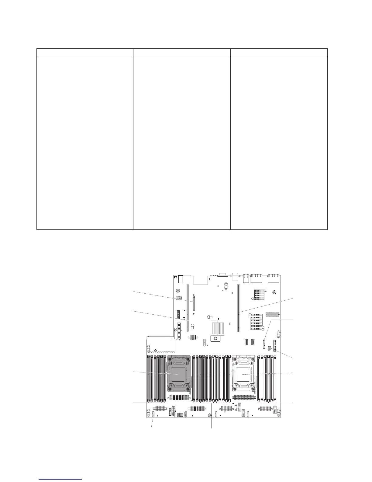
System-board optional device connectors
The following illustration shows the connectors on the system board for
user-installable options.
Optical drive
connector
USB tape
connector
Microprocessor 1
Microprocessor 2
Optional PCI
riser connector 1
Optional PCI
riser connector 2
Optional
10G Ethernet
card connector
DIMM 1-6
DIMM 19-24
DIMM 7-18Fan 4
connector
38 System x3650 M4 Type 7915: Installation and User’s Guide
 Loading...


