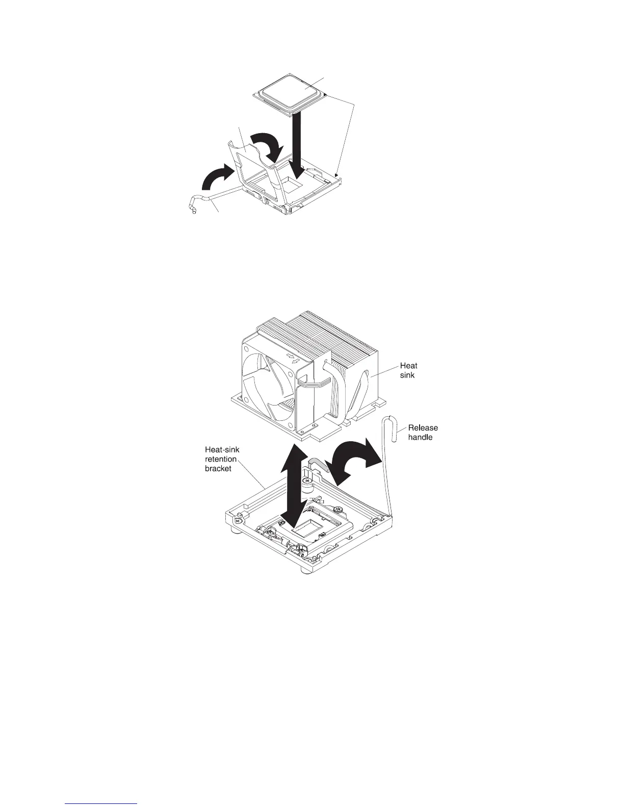
Microprocessor
Alignment
marks
Microprocessor
bracket frame
Microprocessor
release lever
6. Install the fan sink:
a. Make sure that the fan sink retention lever is in the fully open position.
Important: Be careful when you handle the microprocessor and fan sink.
Do not contaminate the thermal material between them.
b. Slide the bottom edge of the fan sink under the lower flange of the
retention module; then, place the top of the fan sink onto the top of the
retention module.
c. Close the fan sink retention lever and lock it securely in place.
d. Reconnect the fan sink cable to the system board (see “System-board
internal connectors” on page 16 for the location of the fan-sink connector).
7. Reconnect any cables that you disconnected during the removal of the old
microprocessor.
8. Rotate the drive cage toward the front of the server until it stops; then, lift and
hold the retaining tab on top of the drive cage while you rotate the drive cage
into the chassis until it locks into place.
9. Reinstall the hard disk drives.
212 System x3200 M3 Types 7327 and 7328: Problem Determination and Service Guide

 Loading...