EasyManuals Logo

IBM x3200 M3 7327 User Manual

IBM x3200 M3 7327
282 pages
To Next Page IconTo Next Page
To Previous Page IconTo Previous Page
Page #37 background imageLoading...
Page #37 background image
System-board external connectors
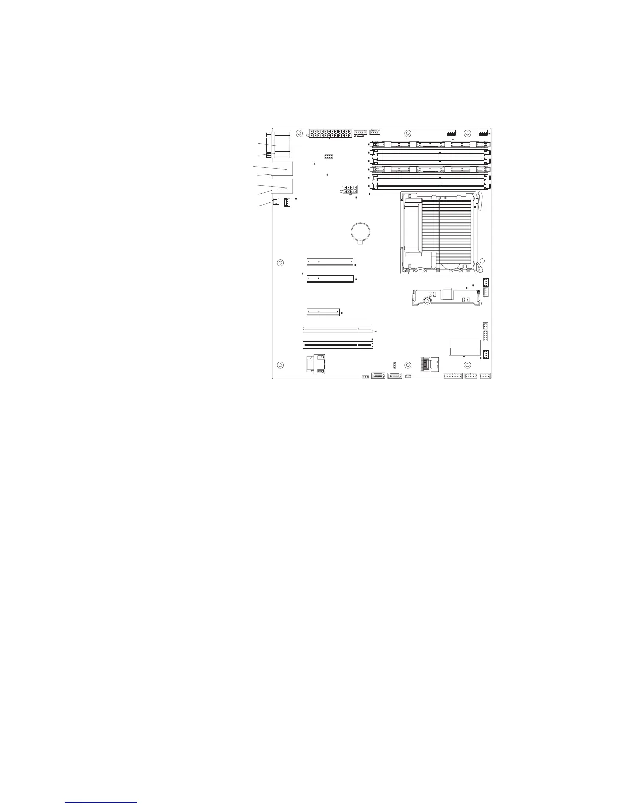
The following illustration shows the external input/output (I/O) connectors on the
system board.
Serial (com1)
Video
Ethernet connector 1
USB connectors 1 & 2
Ethernet connector 2
USB connectors 3 & 4
SW1 (NMI button)
Note: When you disconnect the power source from the server, you lose the ability
to view the LEDs because the LEDs are not lit when the power source is removed.
Before you disconnect the power source, make a note of which LEDs are lit,
including the LEDs that are lit on the operation information panel and LEDs inside
the server on the system board.
Chapter 2. Introduction 17

Table of Contents

Questions and Answers:

Question and Answer IconNeed help?

Do you have a question about the IBM x3200 M3 7327 and is the answer not in the manual?

IBM x3200 M3 7327 Specifications

General IconGeneral
Form FactorTower
Processor Sockets1
ChipsetIntel 3420
MemoryUp to 32 GB
Memory Slots4
StorageUp to 8 TB
Hard Drive Bays4
ProcessorIntel Xeon 3400 series
Memory TypeDDR3
RAID SupportRAID 0, 1, 10
NetworkDual Gigabit Ethernet
Expansion Slots4
Operating System SupportWindows Server, Red Hat Enterprise Linux, SUSE Linux Enterprise Server
Drive Bays4 total (3.5-inch)

Related product manuals