31
PREPARING THE
APPLIANCE
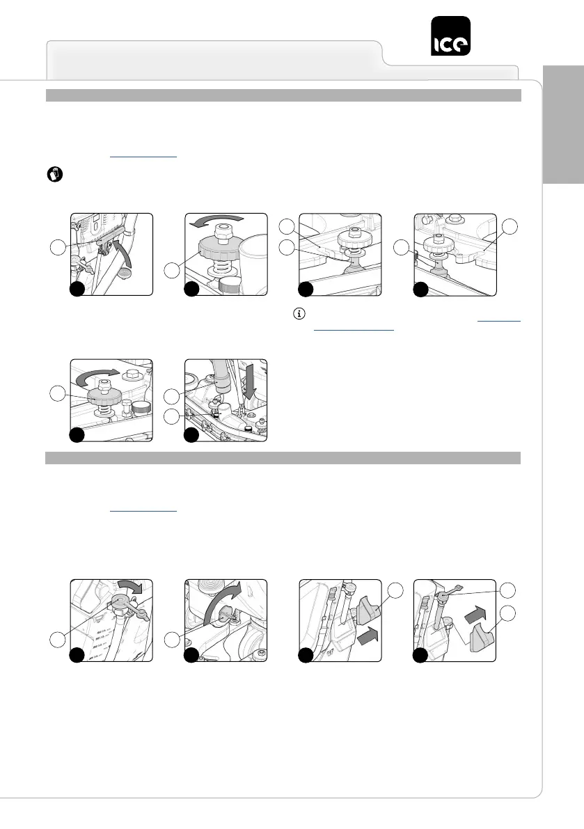
ASSEMBLING THE SQUEEGEE
For packaging reasons, the squeegee unit is supplied disassembled
from the device, and must be assembled on the squeegee support
as follows:
1. Take all necessary steps to ensure that the device is in a safe
condition (see “MACHINE SAFETY”).
ATTENTION: these operations must be carried out using
protective gloves to avoid any possible contact with the edges
or tips of metal objects.
2. Make sure the squeegee unit support is raised off the oor. If
it isn't, turn the squeegee control lever (1) on the back of the
machine in the direction shown by the arrow (Fig.1).
3. Unscrew the knobs (2) in the squeegee unit pre-assembly (Fig.2).
4. First insert the left pin (3) on the squeegee body into the left slit
(4) in the squeegee support (Fig.3), making sure that the washer
and spring adhere to the top of the squeegee support.
5. Insert the right pin (5) on the squeegee body into the right slit (6)
in the squeegee support (Fig.4), making sure that the washer and
spring adhere to the top of the squeegee support.
6. Tighten the knobs (2), ensuring that the washer and spring
adhere to the top part of the squeegee support (Fig.5).
7. Insert the vacuum tube (7) in the sleeve (8) in the squeegee unit
(Fig.6).
ATTENTION: the squeegee has been adjusted beforehand,
nevertheless if it is necessary read the section “ADJUSTING
THE SQUEEGEE UNIT”.
FILLING THE SOLUTION TANK WITH WATER
Before lling the solution tank, carry out the following steps:
1. Take the machine to the dedicated solution tank lling area.
2. Take all necessary steps to ensure that the device is in a safe
condition (see "MACHINE SAFETY’”).
3. Check that the solution tank discharge cap (1) is open. If it isn't,
open it (Fig.1).
4. Check that the lter plug of the water system (2) at the rear
right part of the machine, has been tightened, and if not turn it
clockwise (Fig.2).
The solution tank can be lled with water in three different ways:
• Removing the cap/measuring device (3) and lling the solution
tank by means of a rubber hose or a bucket (Fig.3).
• Using the ller hose (4) (Fig.4). This supports the water hose on
its own, but be sure to remove the cap/measuring device (3) to
allow adequate air venting.
1 3 5
2
4 6
2
4
1
3
2
8
7
65
1 2
3 4
3
43
1 2